Screen Space Reflections (SSR) Rendering Pipeline
This rendering pipeline is new in Babylon.js 5.51.0 and replaces the Screen Space Reflections Post Process. This is a more efficient and robust method for rendering screen space reflections.
Introduction
Rendering reflections in real time can be done using several methods. Each method has its own advantages and disadvantages. For web technologies, there are two main methods:
- Use of a mirror texture:
- Advantages: renders perfect reflections on a plane.
- Disadvantages: limited to one reflection direction and complexity increases according to the geometry of the scene.
- Use of SSR post-processing :
- Advantages: makes all reflections possible in all directions and the complexity only depends on the screen resolution (like all post-processing).
- Disadvantages: limited to what the camera sees.
Ray tracing is also used in some games to render reflections. However, it is not yet available in web technologies.
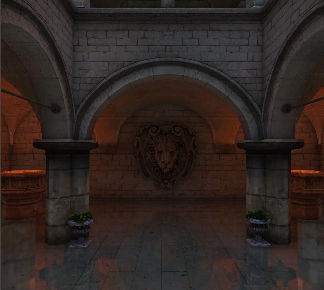
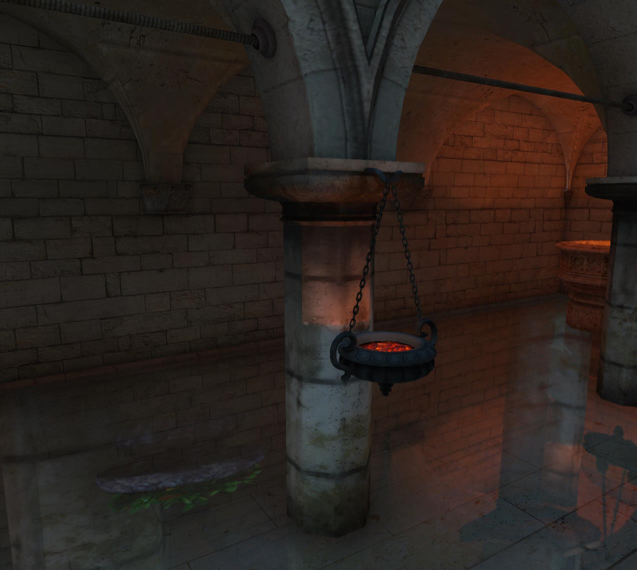
Here is a comparison of the rendering with and without the activation of the SSR rendering pipeline:
| With SSR | Without SSR |
|---|---|
With SSR 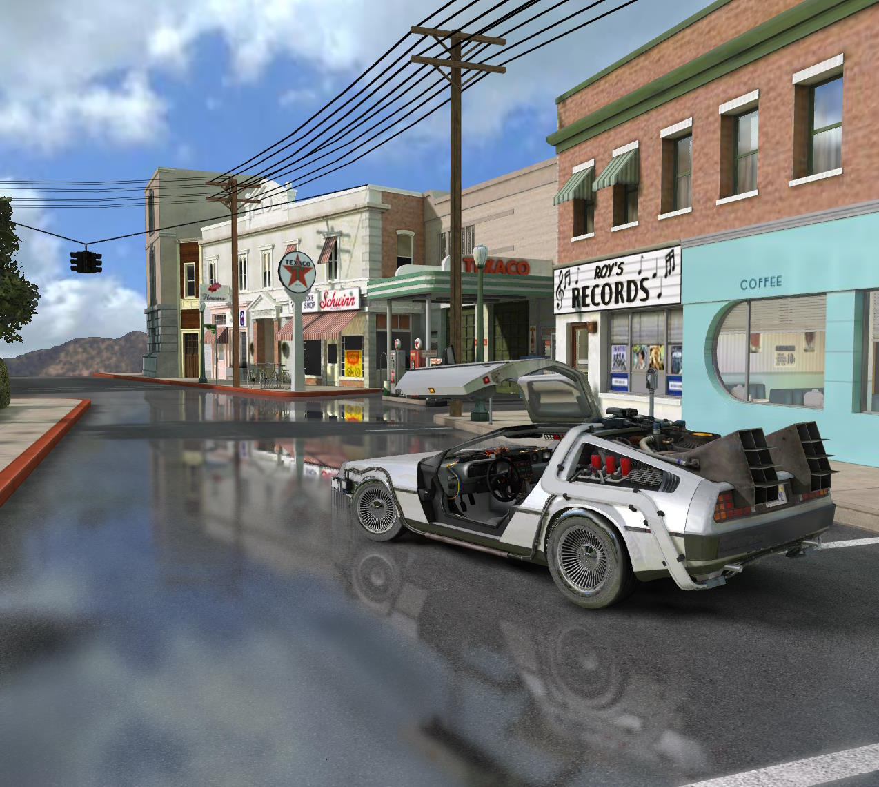 | Without SSR 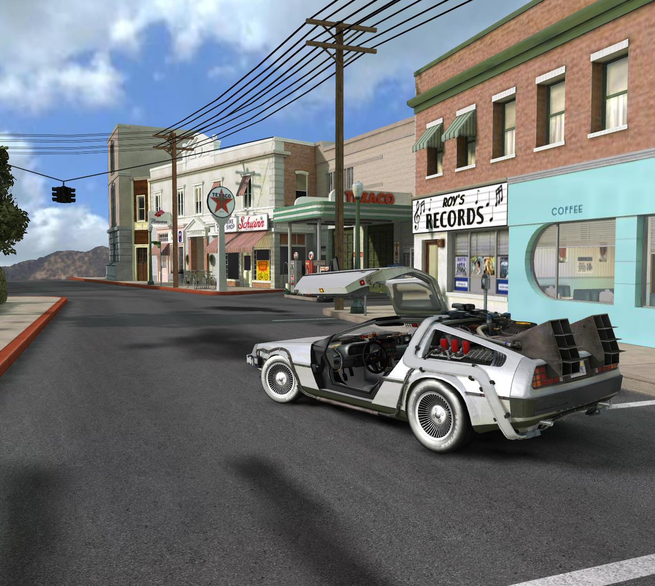 |
With SSR  | Without SSR 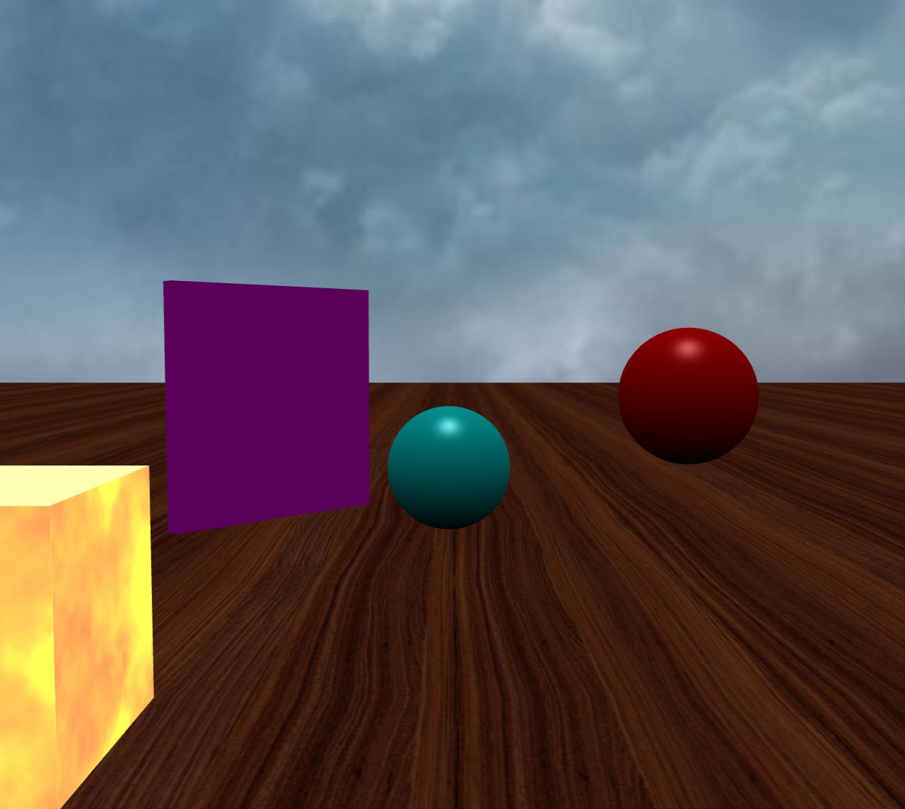 |
With SSR 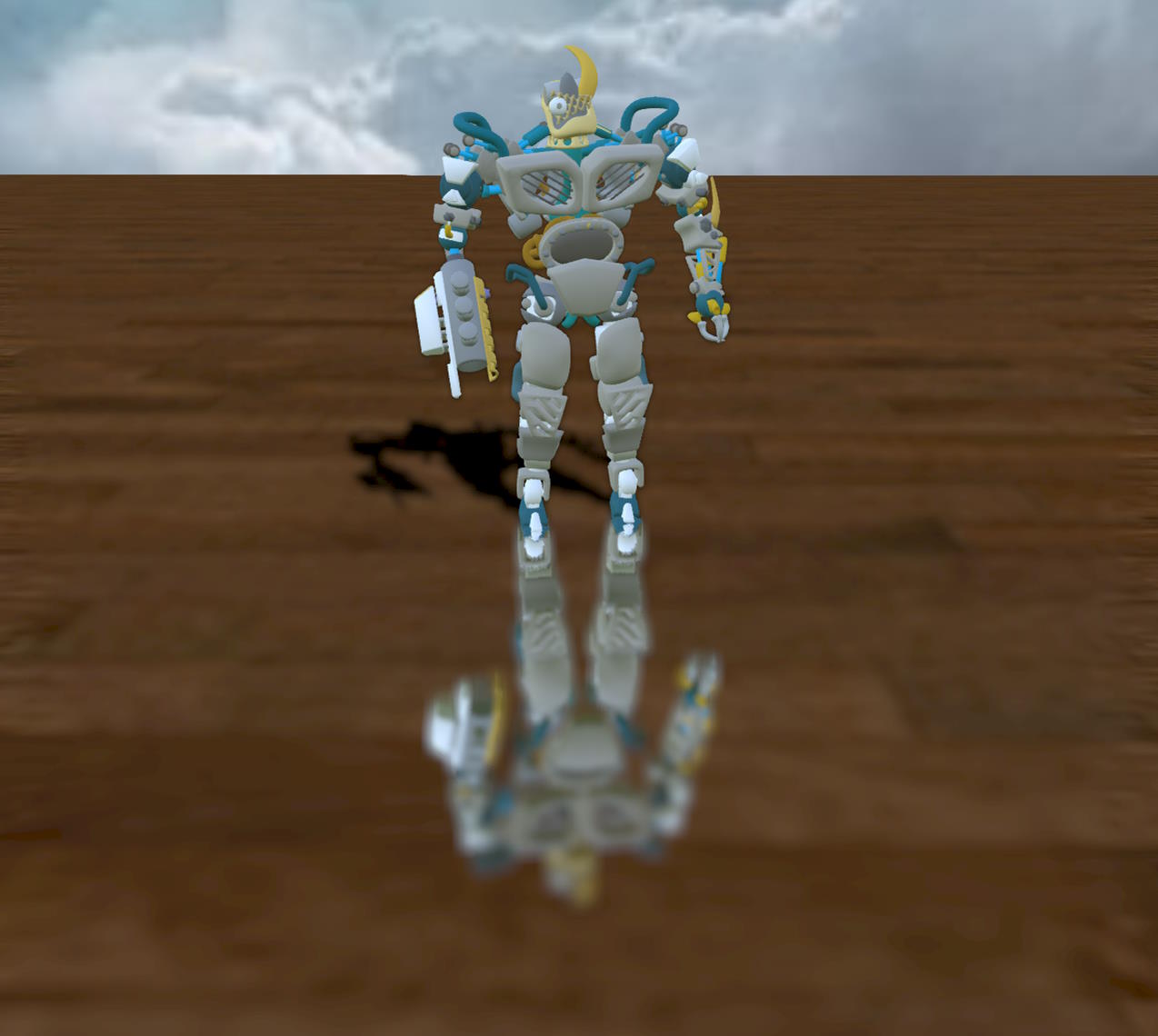 | Without SSR 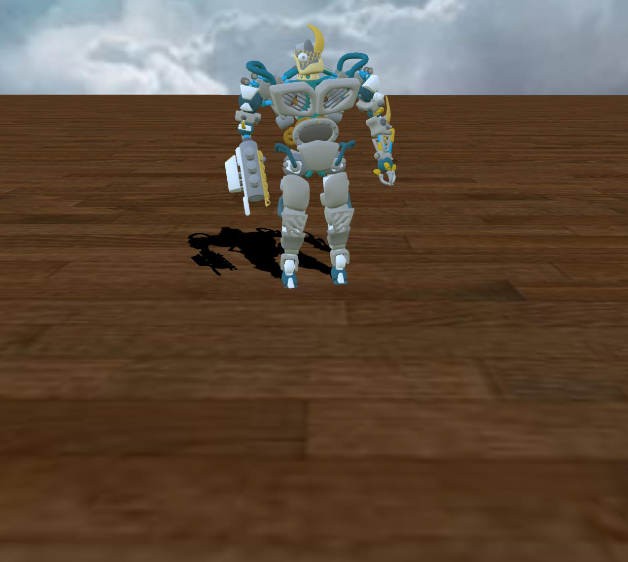 |
Here are the playgrounds that generated the above images:
- SSR Rendering Pipeline Example (Hill Valley)
- SSR Rendering Pipeline Example (Balls)
- SSR Rendering Pipeline Example (BrainStem)
Prerequisites
To render reflections using the SSR rendering pipeline, the device must support WebGL 2 or WebGPU. If it does not, the render pipeline will work as a simple pass-through.
For any reflective geometry in your scene, the SSR pipeline needs to know its "reflectivity" properties. To provide this information, your reflective meshes must contain:
- For a Standard Material: a specular color (
material.specularColor), and optionally a specular texture (material.specularTexture). These elements will be used to know how much the object reflects for each pixel. Important: by default, the specular color of a standard material is(1,1,1), so the material is totally reflective! If you don't want your material to be reflective, set the specular color to(0,0,0). - For a PBR material: the
metallicproperty and optionally ametallicTexturefor the metallic/roughness workflow, and thereflectivityColorproperty and optionally areflectivityTexturefor the specular/glossiness workflow. The roughness property (in the metallic/roughness workflow) or the micro-surface property (in the specular/glossiness workflow) will also be used to blur the reflection (see below for more details).
In the case of PBR, the reflective color is never black, there are always reflections, which means that the SSR effect will be applied to all pixels on the screen! This can be costly in performance for zero benefit, because when the reflective color is low, you usually won't see any difference between applying or not applying the SSR effect (it also depends on the roughness property). This is why the SSR pipeline provides a reflectivityThreshold property, which will disable the effect for pixels whose reflective color is at or below a certain threshold. The default value is 0.04, which is the default reflective color you get when metallic = 0.
Important: only standard and PBR materials are supported by the SSR effect!
Creating the SSR rendering pipeline
Just create an instance of BABYLON.SSRRenderingPipeline :
const ssr = new BABYLON.SSRRenderingPipeline( "ssr", // The name of the pipeline scene, // The scene to which the pipeline belongs [scene.activeCamera], // The list of cameras to attach the pipeline to false, // Whether or not to use the geometry buffer renderer (default: false, use the pre-pass renderer) BABYLON.Constants.TEXTURETYPE_UNSIGNED_BYTE, // The texture type used by the SSR effect (default: TEXTURETYPE_UNSIGNED_BYTE));You can easily enable/disable the SSR effect by setting the isEnabled property of the pipeline.
How SSR works
A basic understanding of the algorithm will help you understand how to configure the SSR rendering pipeline for best results.
The algorithm is based on the following steps:
- Render the scene in multiple render targets, using either the geometry buffer or the pre-pass renderer. We need to generate the normal, depth and reflectivity buffers.
- For each pixel in the screen, if it is reflective:
- Calculate the reflection vector of the camera-to-pixel direction and trace a ray from the pixel's position in that direction. To calculate the reflection vector, we need the normal at this pixel, that's why we need to generate this buffer. Moreover, this calculation is done in the camera space (3D space), so we need to convert the 2D coordinates of the pixel into 3D (thanks to the depth buffer).
- If the ray intersects an object, we get the color of this object from the color texture.
- If the ray does not intersect anything:
- we use the color from
SSRRenderingPipeline.environmentTextureas the hit color if a texture is provided. - we simply use the color of the pixel if no environment texture is provided.
- we use the color from
- If blur is not enabled, we blend the hit color with the pixel color to generate the final color. By default, the blending is done using the reflectivity of the object at that pixel (there's a new option in 6.5.1 (
useFresnel) that will blend using the fresnel coefficient). The calculation of the intersection is done by marching the ray (which means that we advance the ray step by step and calculate a new 3D point at each step) in the screen space, using the depth buffer to know if the ray hit an object or not. In this way, we can calculate the position of the intersected object in camera space (3D) but move forward in 2D space so as not to spend resources in iterations that would project the current point of the ray on the same pixel as the previous iteration. - If blur is enabled, we simply store the SSR effect and not the final pixel color. We will blur the SSR effect in one more pass (see next step).
- If blur is enabled, we blur (in two passes - horizontal and vertical) the result of the SSR pass and merge it with the original scene in a final pass.
Regarding some properties of the SSR pipeline:
- In step 2, the
reflectivityThresholdproperty is used to know whether a pixel is reflective or not. - In step 2.1:
- The starting point of the ray is shifted to avoid self-collision intersections and erroneous reflections. The
selfCollisionNumSkipproperty controls the number of iterations to skip at the start before considering an intersection legitimate. A value of 1 works well in most cases, but it is sometimes necessary to increase it to 2 or 3 to avoid certain rendering artifacts. - If blur is not enabled, the starting point of the ray is jittered to account for the roughness of the surface. The intensity of the jitter is controlled by the
roughnessFactorproperty (default: 0.2).
- The starting point of the ray is shifted to avoid self-collision intersections and erroneous reflections. The
- At step 2.2:
- The ray is moved in 3D space only up to
maxDistance(default: 1000) units from the pixel position (3D). Note that when frustum clipping is enabled (clipToFrustum = true, which is the default), the ray is clipped to the camera frustum, which may reduce the value ofmaxDistancefor that ray. - The ray is moved in 2D space up to
maxSteps(default: 1000) iterations. The number of pixels that are moved in each iteration is given bystep(default: 1). When theenableSmoothReflectionsproperty istrue, an additional calculation is performed to compute a more accurate intersection point. This extra step will only occur ifenableSmoothReflections = trueandstep > 1. - The
thicknessproperty is used to give thickness to objects during the intersection calculation. See below for more explanation of thethicknessparameter.
- The ray is moved in 3D space only up to
- In step 2.5,
roughnessFactoris used as a global roughness factor applied to all objects. It can help blur reflections even when the roughness of some surfaces is 0. - In step 3,
blurDispersionStrength(default: 0.03) andblurQuality(default: 2) are used to control the strength and quality of the blur dispersion effect.
Debugging SSR scenes
An important setting in the SSR pipeline is the debug property. It can help you understand what is going on in your scene, and we will use it a lot in the following sections.
Simply set it to true to enable a special color rendering of the SSR effect:
ssr.debug = true;For example
| Without debug | With debug |
|---|---|
Without debug | With debug 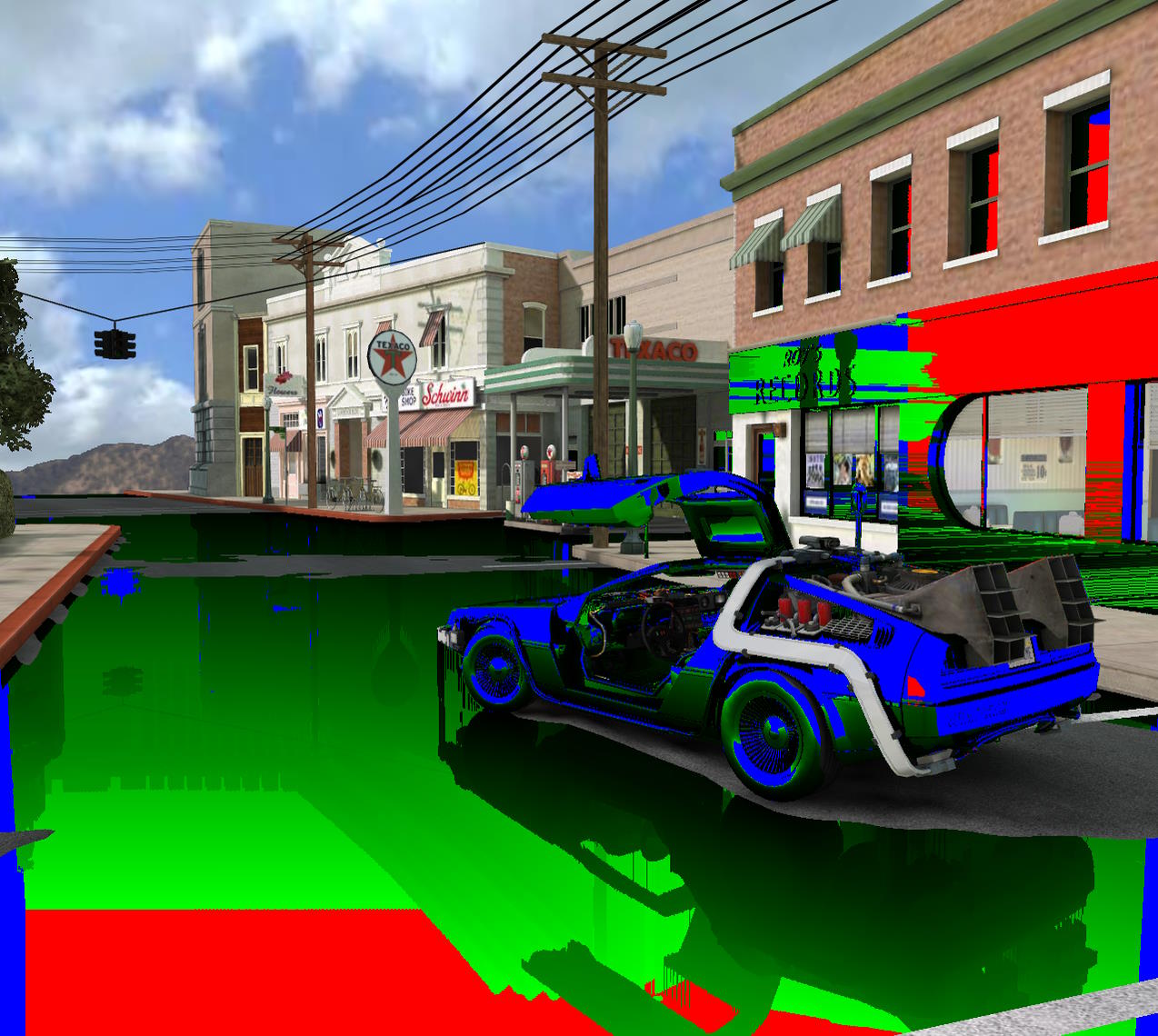 |
The meaning of the colors is as follows:
_ blue: the ray has reached the maximum distance (we have reached maxDistance)
_ red: the ray ran out of steps (we have reached maxSteps)
_ yellow : the ray has left the screen. By default, frustum clipping is on, so you shouldn't see this color much.
_ green : the ray has intersected a surface. The brightness of the green color is proportional to the distance between the origin of the ray and the point of intersection: a lighter green means more calculations than a darker green. The brightness is directly proportional to the number of steps the main loop had to execute to find an intersection (debug.green = num_steps / maxSteps): if we did not find an intersection within maxSteps, a red color is generated instead of a full green.
If possible, you should try to get as few red pixels as possible, as this means that we have executed all the iterations of the loop before stopping without finding an intersection.
You can trade red pixels for blue pixels by increasing the value of step, which will favor speed over quality, so it's a balance to be found depending on your scene and the final result you expect.
Geometry buffer or Pre-Pass renderer
The SSR rendering pipeline can use either the Geometry Buffer Renderer or the Pre-Pass Renderer to render the scene. The default is to use the pre-pass renderer, but you can force the use of the geometry buffer renderer by setting the forceGeometryBuffer parameter in the constructor to true.
You don't need to worry about the internal details of these renderers, but choosing one or the other can have an impact on the final rendering.
Using MSAA
You would normally choose the pre-pass renderer because the reflectivity color is calculated more accurately than with the geometry buffer renderer and the performance is better overall, but if you want to use MSAA as an anti-aliasing method, the geometry buffer renderer may be a better choice. This is because MSAA can cause artifacts when used with the pre-pass renderer.
Here is an example of a scene using MSAA with the geometric buffer and the pre-pass renderer:
| Geometry Buffer | Pre-Pass |
|---|---|
Geometry Buffer  | Pre-Pass 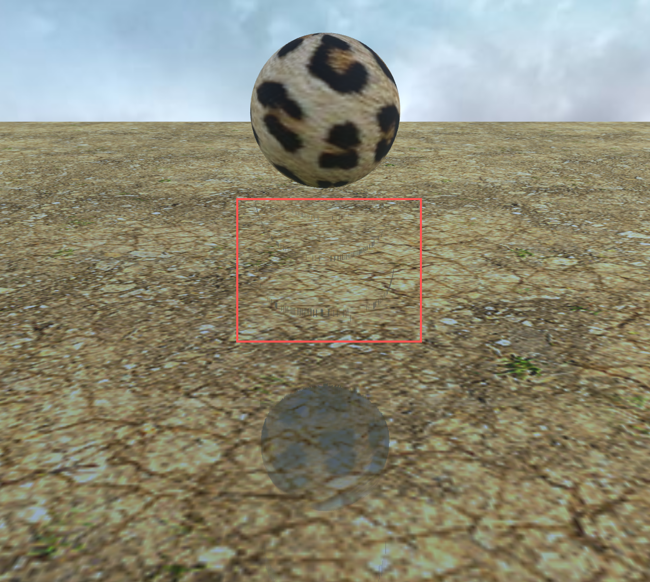 |
Look inside the red rectangle to see the artifacts.
It's even worse if you turn on the automatic thickness calculation:
| Geometry Buffer | Pre-Pass |
|---|---|
Geometry Buffer  | Pre-Pass 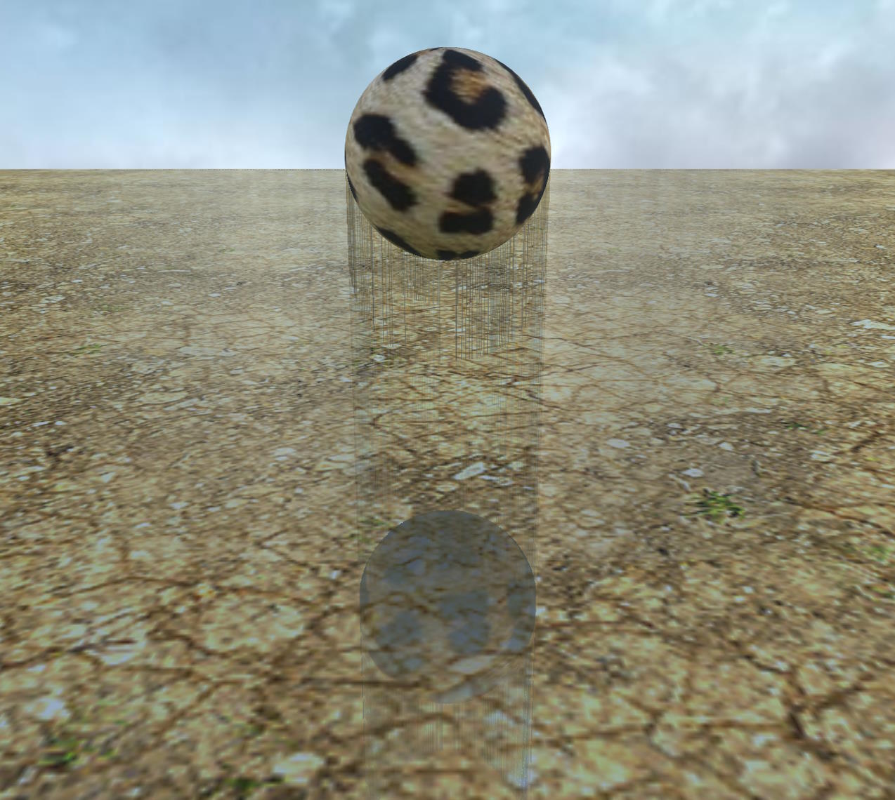 |
Note that the artifacts depend on your scene. Try to spot them in the image on the right:
| Pre-Pass without MSAA | Pre-Pass with MSAA |
|---|---|
Pre-Pass without MSAA 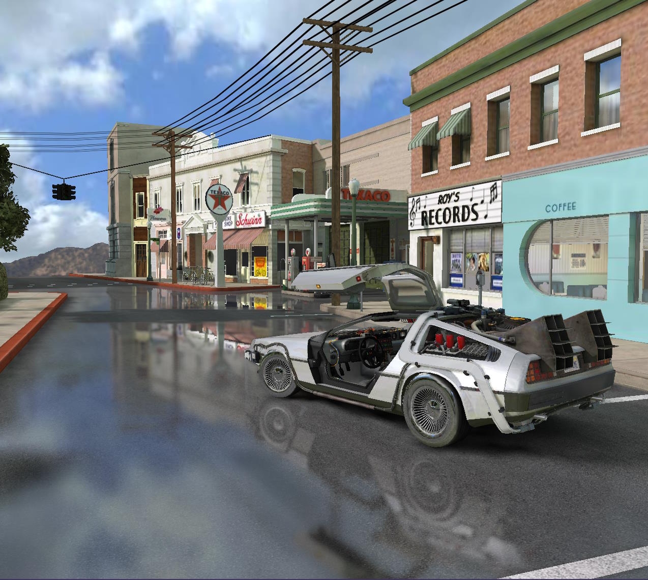 | Pre-Pass with MSAA 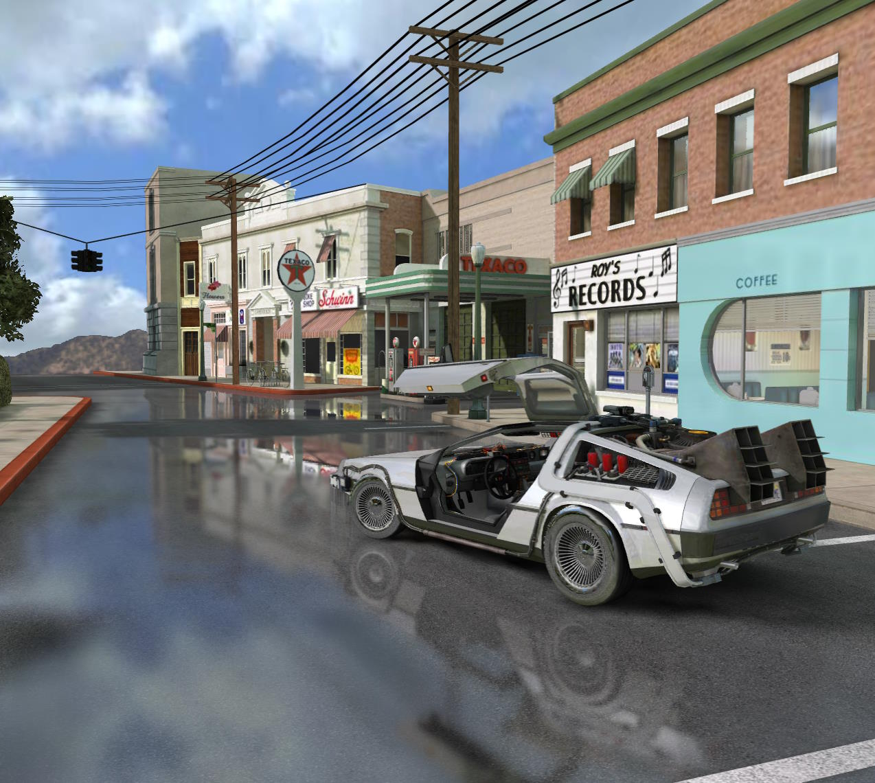 |
The artifacts are barely visible, so in this scene using MSAA might be a valid option.
Instead of MSAA, you can use FXAA if you want anti-aliasing in the case of pre-pass rendering:
| Geometry Buffer with MSAA | Pre-Pass with FXAA |
|---|---|
Geometry Buffer with MSAA | Pre-Pass with FXAA 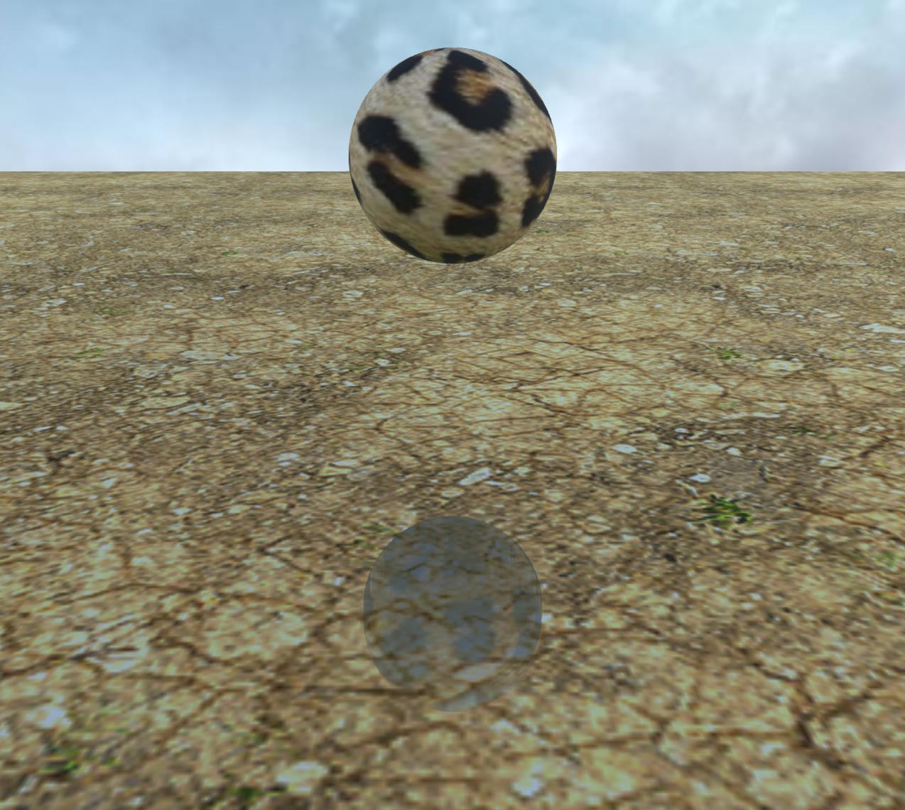 |
Here is the PG used in these examples: Comparison of the MRT renderers
Depth texture type
Also, one thing to note about the pre-pass renderer is that you have the option to use 16-bit floating textures for the depth texture, to save memory space for example (the geometry buffer renderer always uses a 32-bit floating texture). This can lead to rendering artifacts, depending on your scene:
| 32 bits float depth texture | 16 bits float depth texture |
|---|---|
32 bits float depth texture 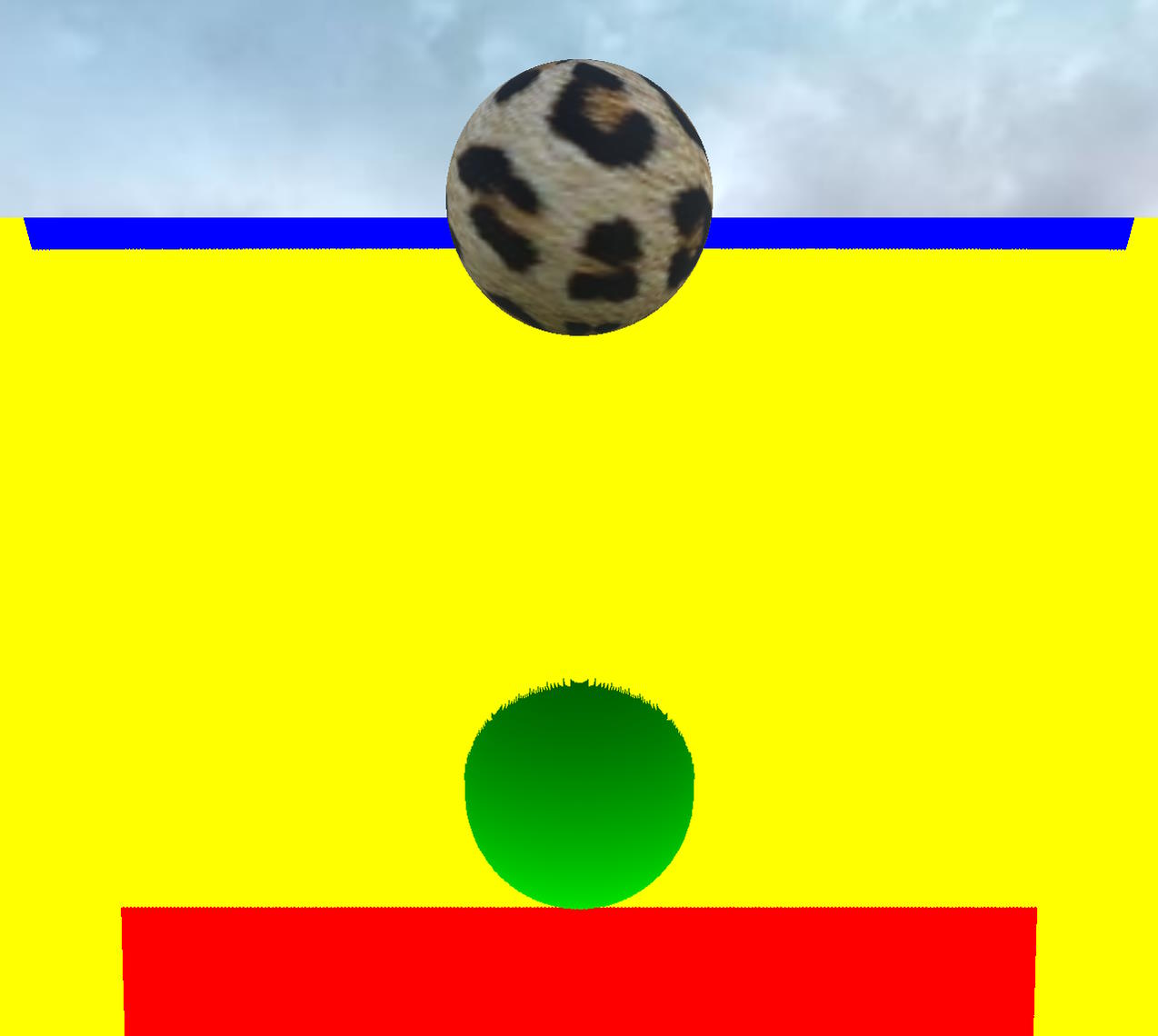 | 16 bits float depth texture 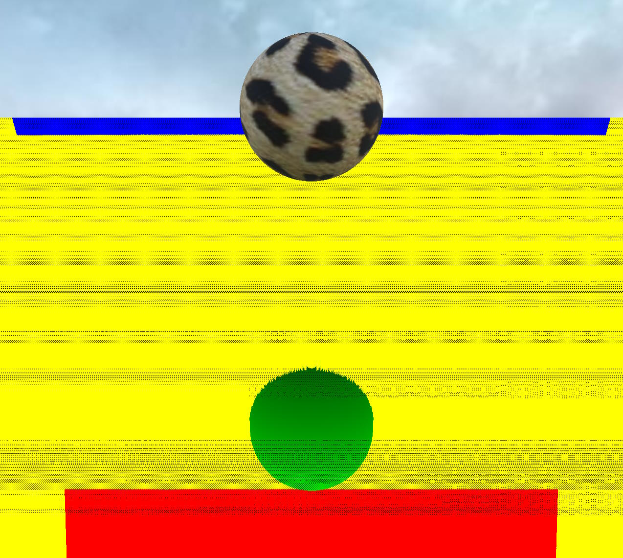 |
Note: ssr.clipToFrustum has been set to false to take these screenshots because the artifacts are more visible with a yellow background than with a blue one!
You get these artifacts because there is less precision in the depth buffer and therefore you get more self-collisions between the reflected ray and the actual surface from which the ray is shot (see section 2.1 in How SSR is working).
You can solve the problem by keeping the default texture with a depth of 32 bits or by increasing selfCollisionNumSkip :
ssr.selfCollisionNumSkip = 2;
Here is the corresponding PG for this screenshot: 16 bits float depth texture and skip to 2
Note that currently WebGPU does not support filtering for 32-bit floating point textures, so the depth texture is a 16-bit floating point texture!
Description of SSR parameters
In the following sections, we will describe the most important parameters of the SSR rendering pipeline, as it is not always easy to choose the right values for each parameter, or to know what impact it has on the final rendering.
Thickness
In step 2.2 of the SSR algorithm, we know if the ray has hit an object when:
- the depth of the current point of the ray is farther away than the depth of the pixel on which this point is projected (this depth is read from the depth buffer). This means that the current ray point is "behind" the object that was rendered in the depth buffer at that point. Note that the depth increases for objects further away from the camera.
- The depth of the previous point of the ray is closer than the depth of the pixel on which this point is projected. This means that the previous point of the ray is "in front" of the object that was rendered in the depth buffer at that point
Thus, we know that we have crossed the boundary of the object rendered at the location of this pixel. However, the depth buffer stores only one depth value for each pixel, so we don't know the thickness of an object, which is necessary if we want to calculate accurate intersections. By default we use a constant thickness value, which is set to 0.5 by default. You can change this value by setting the thickness property of the SSR rendering pipeline, and this value will depend on the extent of your scene.
| Thickness 0 | Thickness 0.5 |
|---|---|
Thickness 0 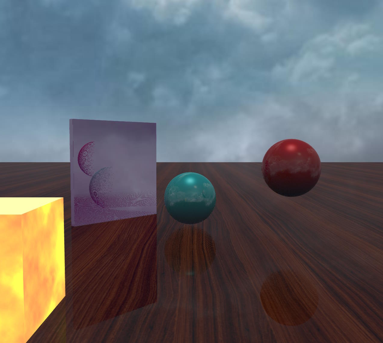 | Thickness 0.5  |
| Thickness 1 | Thickness 4 |
|---|---|
Thickness 1 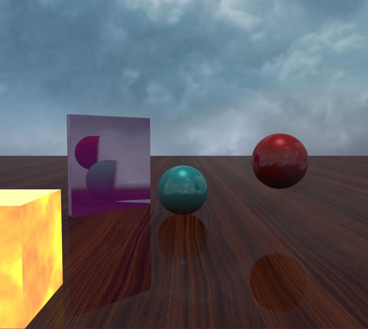 | Thickness 4 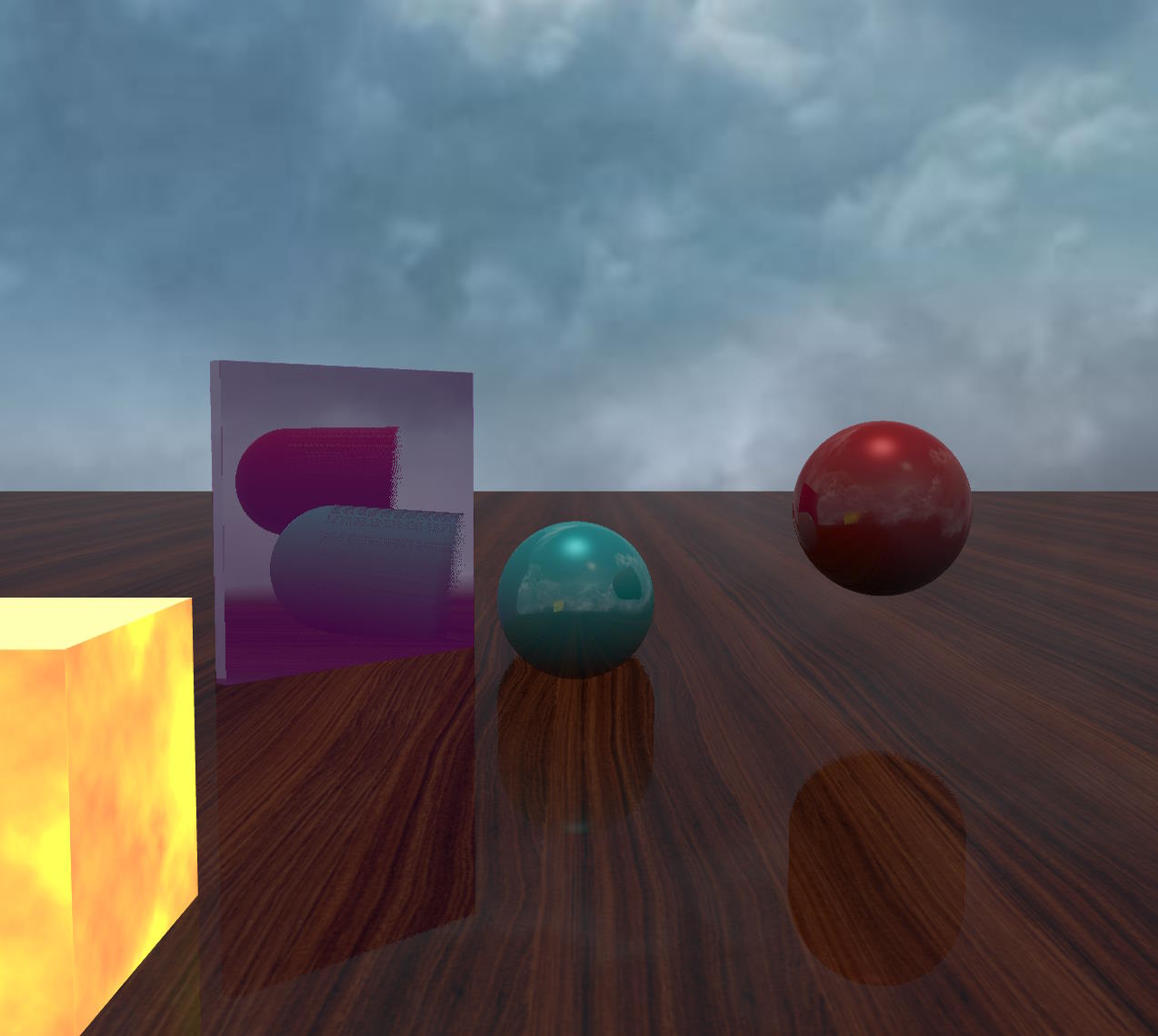 |
As you can see in the mirror and on the floor, the reflections of the objects expand but only in a linear way, the shape of the sphere is not preserved because we use a constant thickness value.
Automatic thickness calculation
The SSR pipeline also supports a more accurate method of calculating thickness, which is to use additional depth rendering to generate the depth of the back faces. In this way, we can calculate the thickness as the difference between the depth value read from this back depth buffer and that read from the front depth buffer:
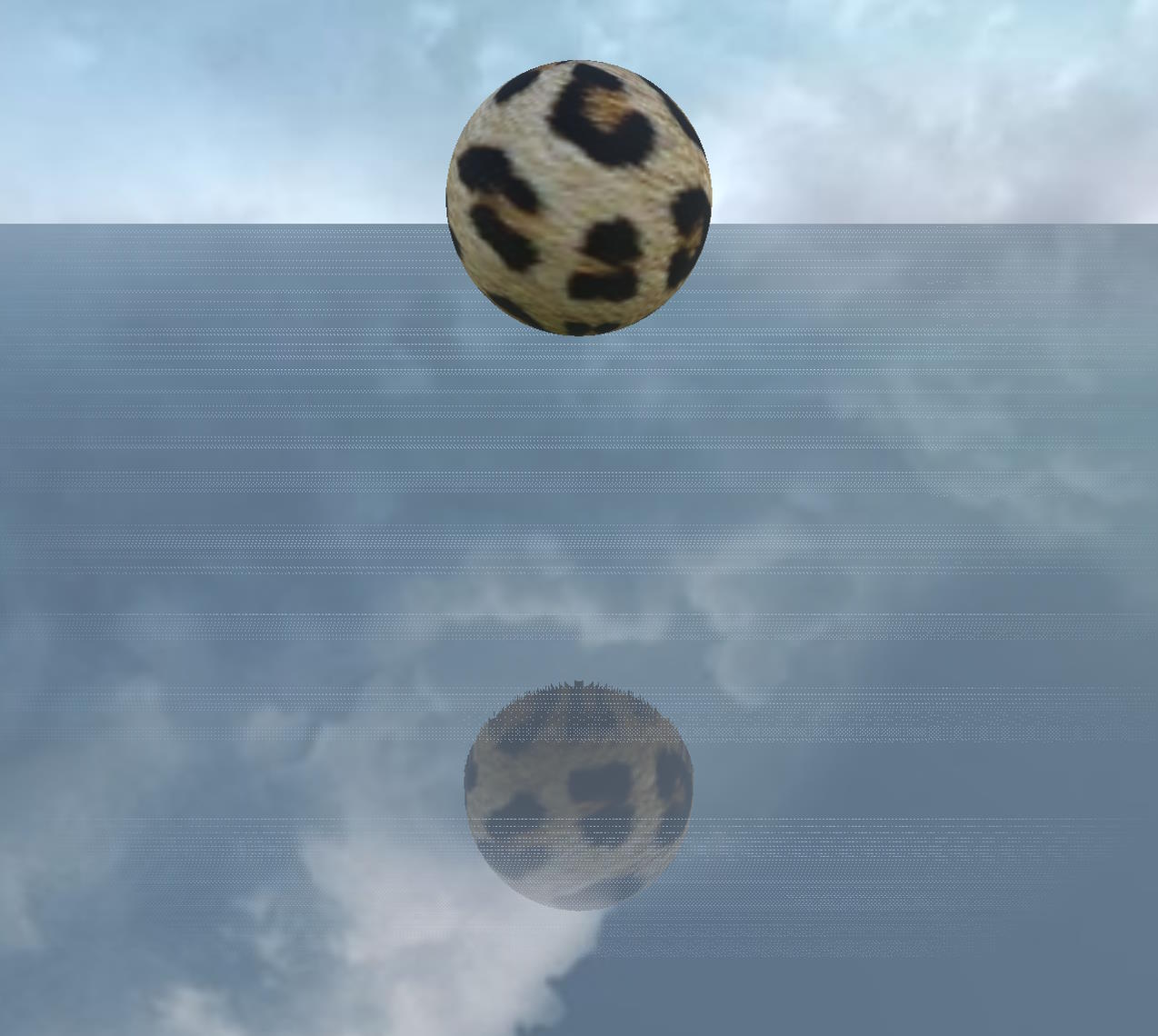
| Thickness 1 | Thickness 0 with automatic thickness computation |
|---|---|
Thickness 1 | Thickness 0 with automatic thickness computation  |
Here is the corresponding PG: SSR Rendering Pipeline Example (Balls)
You enable this mode by setting the enableAutomaticThicknessComputation property of the SSR rendering pipeline to true:
ssr.enableAutomaticThicknessComputation = true;In this mode, thickness is always used as an additional offset, but you can typically use a much lower value, and even 0 works well in many cases.
However, this is not a magic mode, it will not solve all SSR problems and only a single thickness can be calculated this way. Also, it is more demanding in terms of performance because there is additional rendering of the scene to generate the back depth buffer. Sometimes it's better to add a little blur to mask artifacts rather than enabling this mode, which will be lighter on the GPU.
You can reduce the GPU requirements of this mode by setting a value greater than 0 for backfaceDepthTextureDownsample (1 to divide the texture size by 2, 2 to divide it by 3 and so on), which will reduce the size of the depth texture used by the depth renderer. However, this can lead to significant artifacts, so it is always a trade-off between performance and quality and how best you can try to hide the artifacts.
Maximum distance, maximum steps, steps, smooth reflections and clipping to frustum
maxDistance, maxSteps, step and enableSmoothReflections work together, and their impact on the final rendering can be understood by reading the How SSR works section as well as Debugging your SSR scenes.
In summary:
- a ray will not go further than
maxDistance(in 3D space) - a ray will not go further than
maxSteps*steppixels (in 2D space) - If
stepis greater than 1, you can enableenableSmoothReflectionsto compute more accurate intersections and thus improve reflections.
clipToFrustum = true will clip the ray to the camera frustum and should generally be left true, because although it adds some instructions to the shader, it shortens the radius and thus reduces the computation.
step must be a strictly positive integer, as it is a number of pixels.
Reflection intensity
strength and reflectionSpecularFalloffExponent work together to increase or decrease the SSR effect:
- The
strengthparameter will modulate the reflectivity color. - The
reflectionSpecularFalloffExponentparameter is applied after the reflectivity color is modulated by thestrengthparameter.
The formula is as follows:
reflectionMultiplier = pow(reflectivity * strength, reflectionSpecularFalloffExponent);finalColor = color * (1 - reflectionMultiplier) + reflectionMultiplier * SSR;Note: pow is the exponentiation operator.
It is probably best to keep strength = 1 (the default) and change reflectionSpecularFalloffExponent depending on whether you want to enhance the effect (use values less than 1) or reduce the effect (use values greater than 1).
Blurred reflections
You can optionally add a blur pass to SSR reflections (enabled by default). This improves realism when the surface is not a perfect mirror and has roughness, and it also hides some of the flaws in the technique (see How to deal with Artifacts)!
blurDispersionStrength is the main parameter (default: 0.03). When it is set to 0, the blur is disabled: You must set a value greater than 0 to enable it. The range of values is approximately between 0 and 0.1, where 0.1 is already a strong blur effect.
As mentioned above, the blur is based on the roughness of the material:
- for standard materials, the roughness comes from the alpha channel of the specular texture if provided (and is actually
1 - alpha, since the alpha channel stores gloss, not roughness), and is set to 0 otherwise - for PBR materials, it is computed from the
roughnessproperty and optionally areflectivityTexturefor the metallic/roughness workflow, and from themicroSurfaceproperty and optionally areflectivityTexturefor the specular/glossiness workflow.
If the roughness is 0, the blur will have no effect because the surface is perfectly smooth. If you still want to get some blur even in this case, you can use the roughnessFactor property (default: 0.2), which acts as an additional global roughness:
blurDispersionStrength = 0.0, roughnessFactor = 0 | blurDispersionStrength = 0.05, roughnessFactor = 0 |
|---|---|
blurDispersionStrength = 0.0, roughnessFactor = 0 | blurDispersionStrength = 0.05, roughnessFactor = 0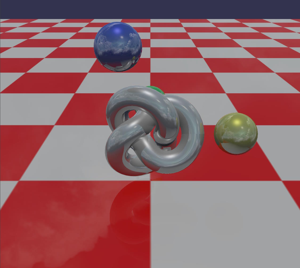 |
In this scene, all materials are standard materials with no specular texture, so their roughness is 0. The two screenshots are identical because the final roughness is 0 for all materials, even if we give a non-zero value to blurDispersionStrength.
blurDispersionStrength = 0.05, roughnessFactor = 0.1 | blurDispersionStrength = 0.05, roughnessFactor = 0.5 |
|---|---|
blurDispersionStrength = 0.05, roughnessFactor = 0.1 | blurDispersionStrength = 0.05, roughnessFactor = 0.5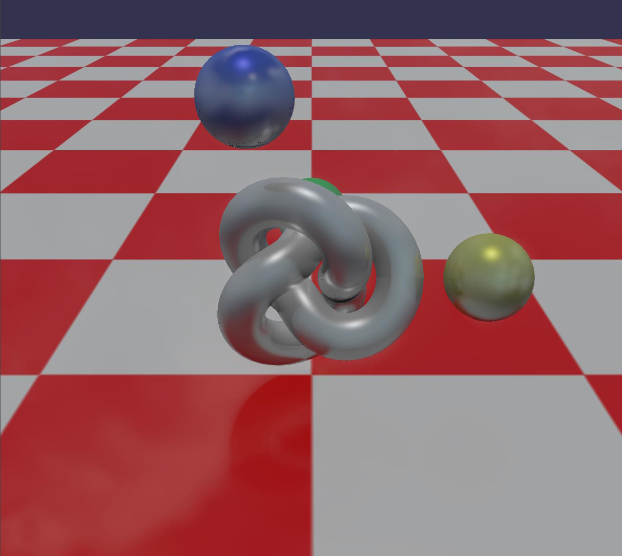 |
By setting a non-zero value to roughnessFactor, you increase the final roughness and the blur now has a visible effect.
Here is the corresponding PG: SSR blur standard material no roughness
The blurDownsample property (default: 0) can be used to reduce the size of the textures used in the blur pass: blurDownsample = 1 will blur at half resolution, blurDownsample = 2 will blur at 1/3 resolution, etc.
Using a value greater than 0 will save some performance and generally have little impact on the final result (at least for small values of blurDownsample), so feel free to use it!
Note that when blur is not enabled, roughnessFactor is used as a factor to modulate the jitter of the starting point of the reflected ray:
no blur, roughnessFactor = 0.05 | no blur, roughnessFactor = 0.2 |
|---|---|
no blur, roughnessFactor = 0.05 | no blur, roughnessFactor = 0.2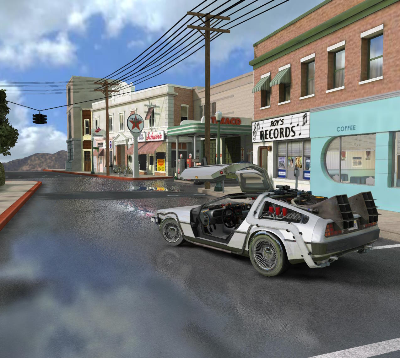 |
As you can see, jittering produces noise, so it's up to you to turn it on or off depending on your needs. Also note that for jittering to be effective, the roughness must be non-zero, as the base value of jittering depends only on the roughness: the roughnessFactor property will only reduce or amplify the effect as a multiplication factor.
Reflectivity Threshold
The reflectivityThreshold parameter is used to discard pixels whose reflectivity value is below a certain threshold. This avoids computing the SSR for pixels that reflect nothing or almost nothing, which can be useful for saving time on the GPU.
For example, in this scene, reflectivityThreshold has been set to 0.001 :
reflectivityThreshold = 0 | Debug view |
|---|---|
reflectivityThreshold = 0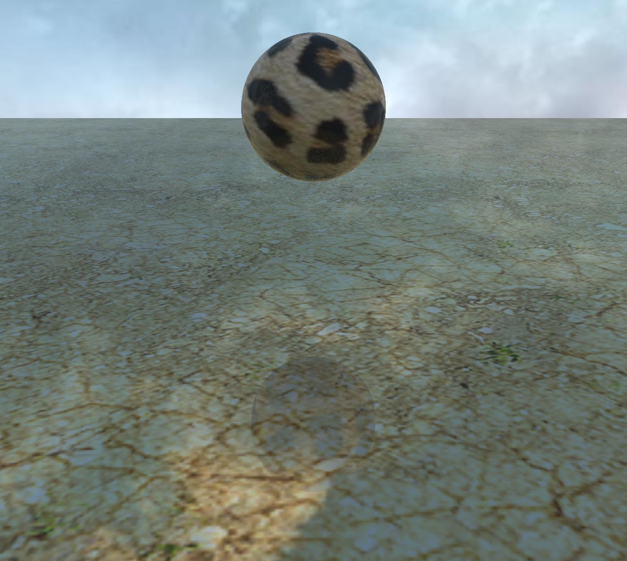 | Debug view 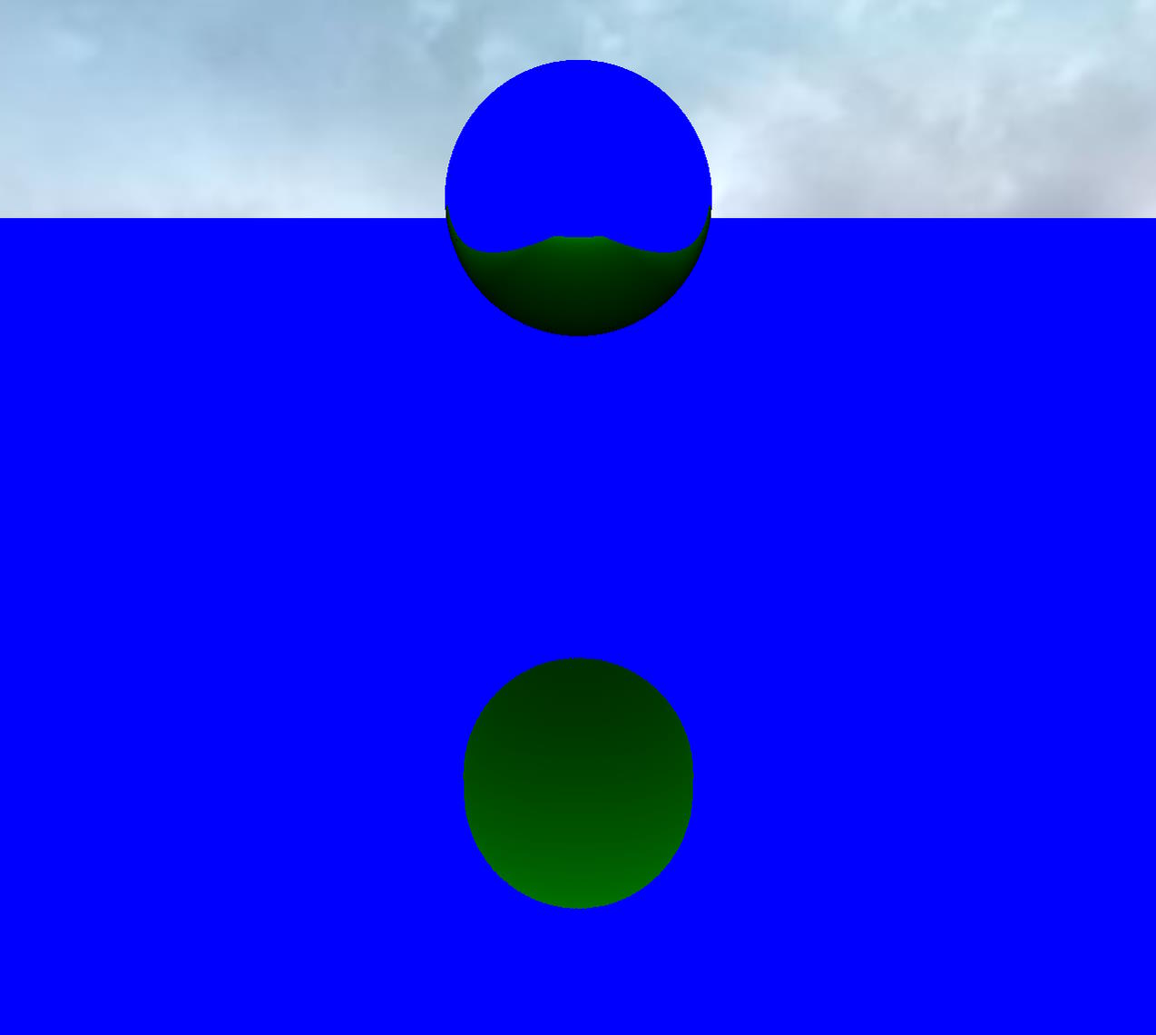 |
Using the debug view, we can see that the reflections are calculated on the sphere, but taking them into account makes no difference visually because the metallic property of the material is 0 and the roughness is 1, so the reflectivity is very low (0.04). By setting reflectivityThreshold to 0.04 (the default value), these reflections are no longer calculated:
Color space
By default, the SSR pipeline expects the input color texture to be in gamma space and will generate its output in gamma space. If for some reason the input is in linear space or you want to generate the output in linear space, you can use these parameters:
inputTextureColorIsInGammaSpace: set it tofalseto indicate that the input color texture is in linear space.generateOutputInGammaSpace: set it tofalseto generate the output in linear space.
Use fresnel
New in 6.5.1 is the ability to use the fresnel coefficient to blend the SSR effect with the original scene. This is controlled by the useFresnel property, which is false by default.
Setting useFresnel to true is more physically accurate, but is more GPU-intensive when you also enable blur (blurDispersionStrength > 0).
This setting can be useful if you want PBR materials to show reflections even when their metallic property is set to 0. By default, reflectivityThreshold = 0.04 because when using material reflectivity instead of Fresnel as the blending factor, reflections are not visible when metallic = 0 (reflectivity is 0.04 in this case). By setting useFresnel = true, you can obtain reflections even when metallic = 0.
Note that the rendering can be quite different if you use useFresnel = true, everything will look more reflective:
useFresnel = false | useFresnel = true |
|---|---|
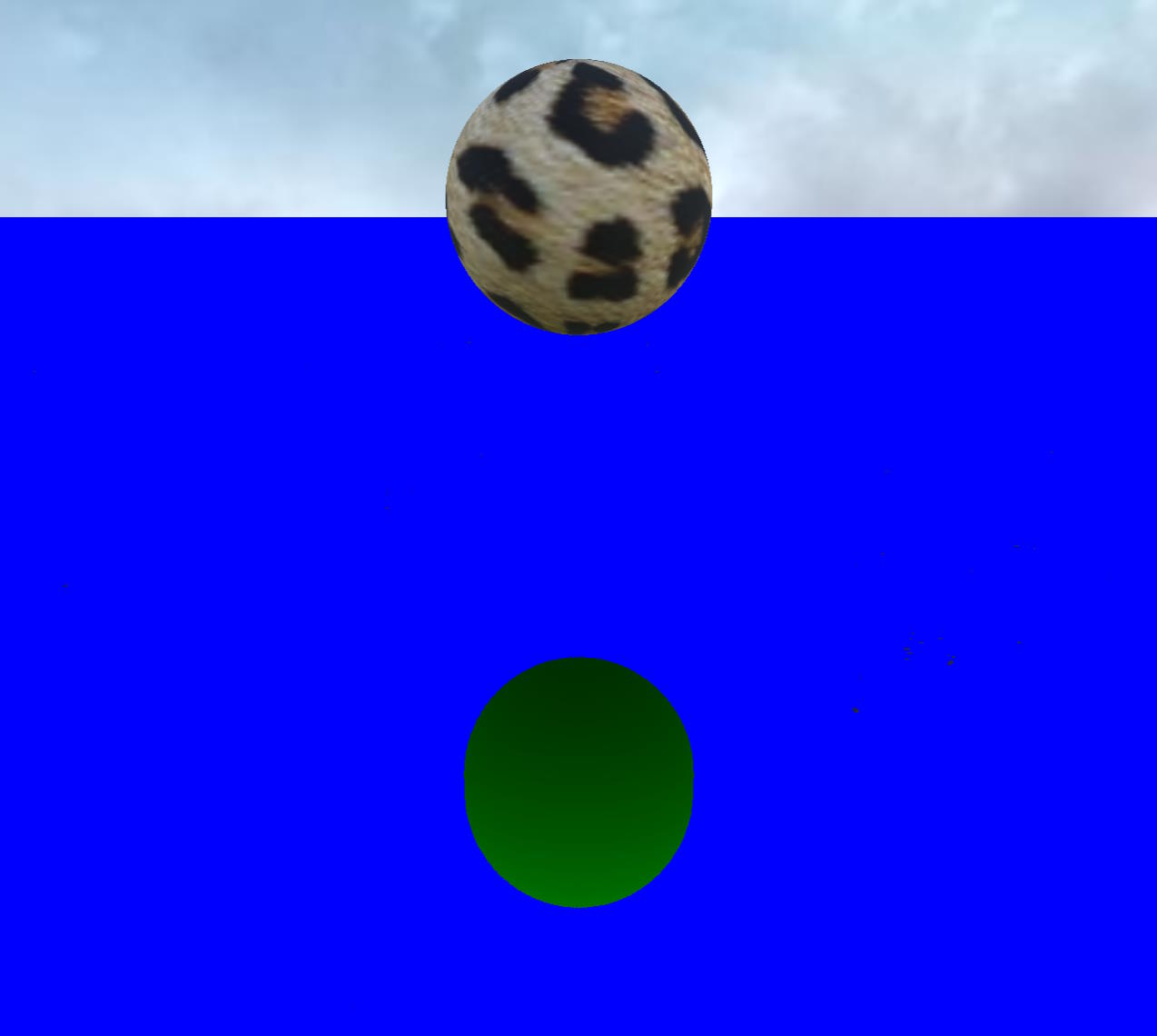
useFresnel = false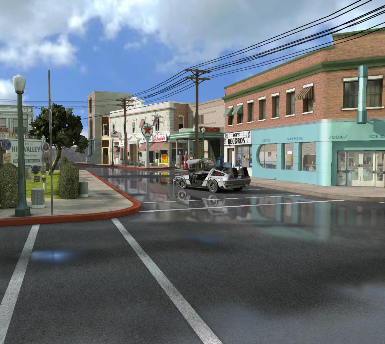 | useFresnel = true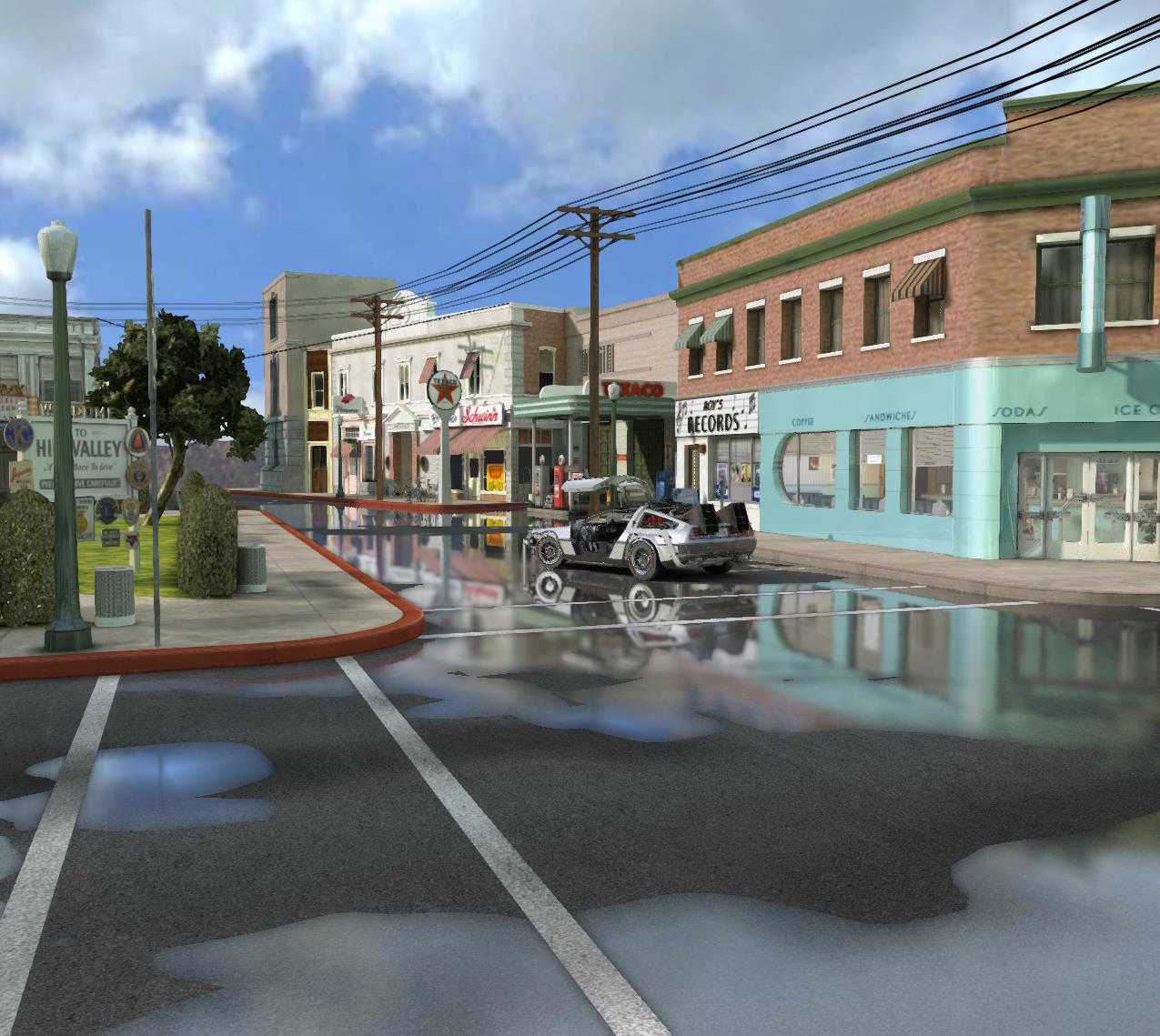 |
useFresnel = false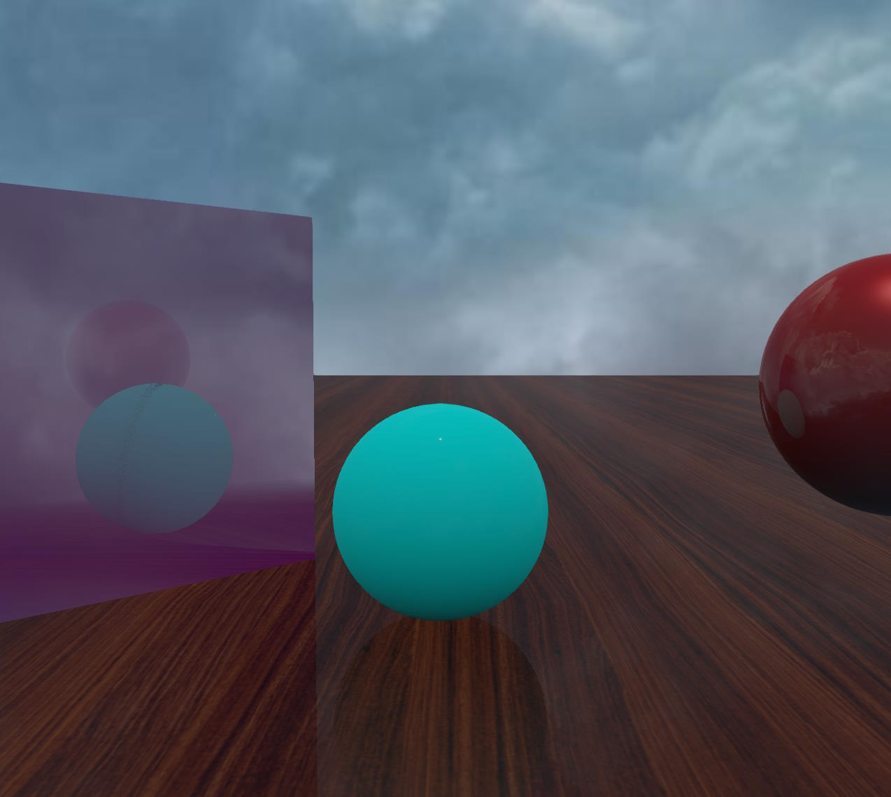 | useFresnel = true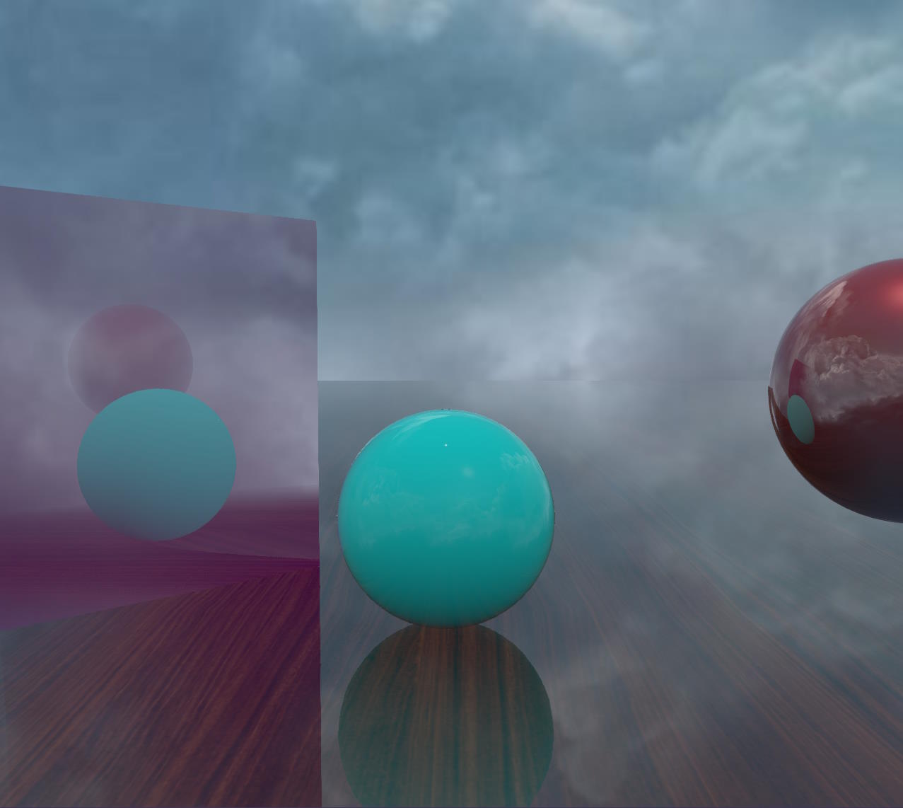 |
In the second example, the blue sphere has a PBR material applied, with metallic = 0 and roughness = 0.
Note that reflectivityThreshold has been lowered to 0.001, as reflections would not have been calculated with the default value of 0.04!
As you can see, there are no visible reflections in the non-Fresnel case, whereas they are visible in the Fresnel case.
How to deal with artifacts
SSR is subject to many artifacts, some of which can be corrected and some of which are inherent to the technique.
This section describes the most common artifacts and explains how to correct them when possible, or how to hide them as much as possible when not.
Artifacts when enabling MSAA with the Pre-Pass renderer
These artifacts and how to correct them have already been described in the Geometry Buffer or Pre-Pass Rendering section, subsection Using MSAA.
As an illustration, here is what artifacts can look like:
Depth buffer accuracy artifacts
These artifacts and how to correct them have already been described in the Geometric buffer or Pre-Pass rendering section, subsection Depth texture type.
As an illustration, here is what artifacts can look like:
Artifacts with transparent meshes
You should note that the Pre-Pass renderer handles transparent meshes better than the geometry buffer renderer when using the opacity texture:
| Geometry Buffer | Pre-Pass |
|---|---|
Geometry Buffer 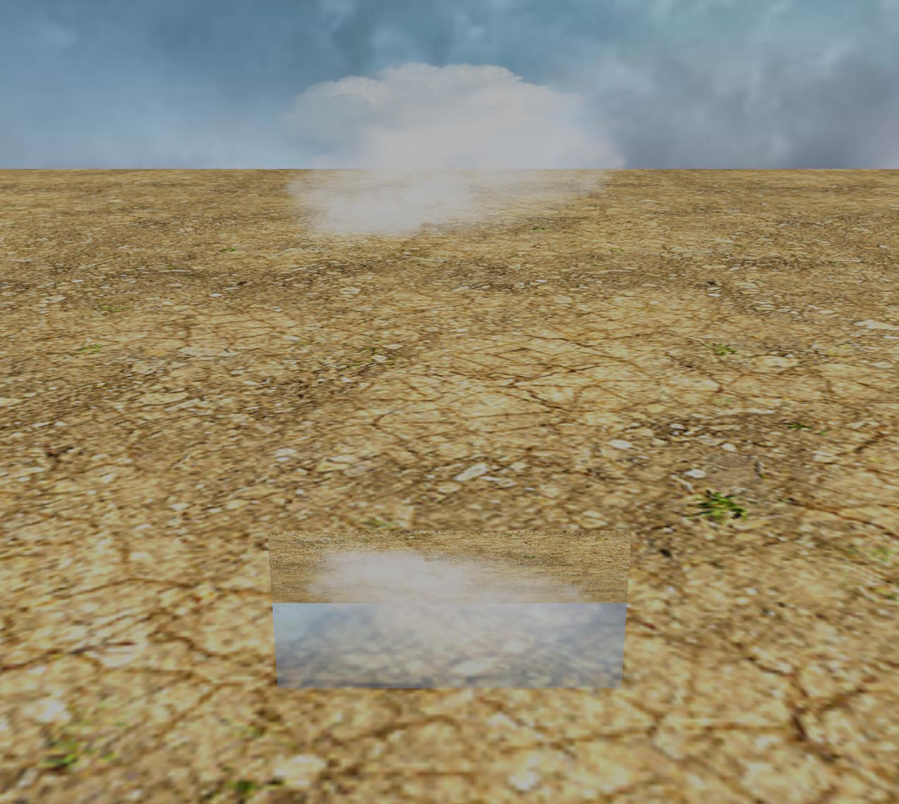 | Pre-Pass 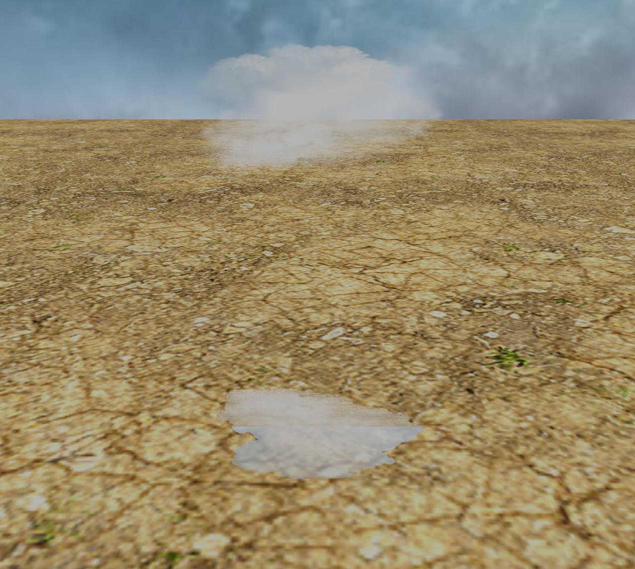 |
It's still not perfect, you can get artifacts even with the pre-pass renderer (exaggerated by putting a full mirror surface) :
Here is the corresponding PG: SSR Artifacts (transparent meshes with prepass renderer)
There is nothing we can do, unfortunately, you will have to be creative to try to hide these defects!
Artifacts when using the automatic thickness calculation
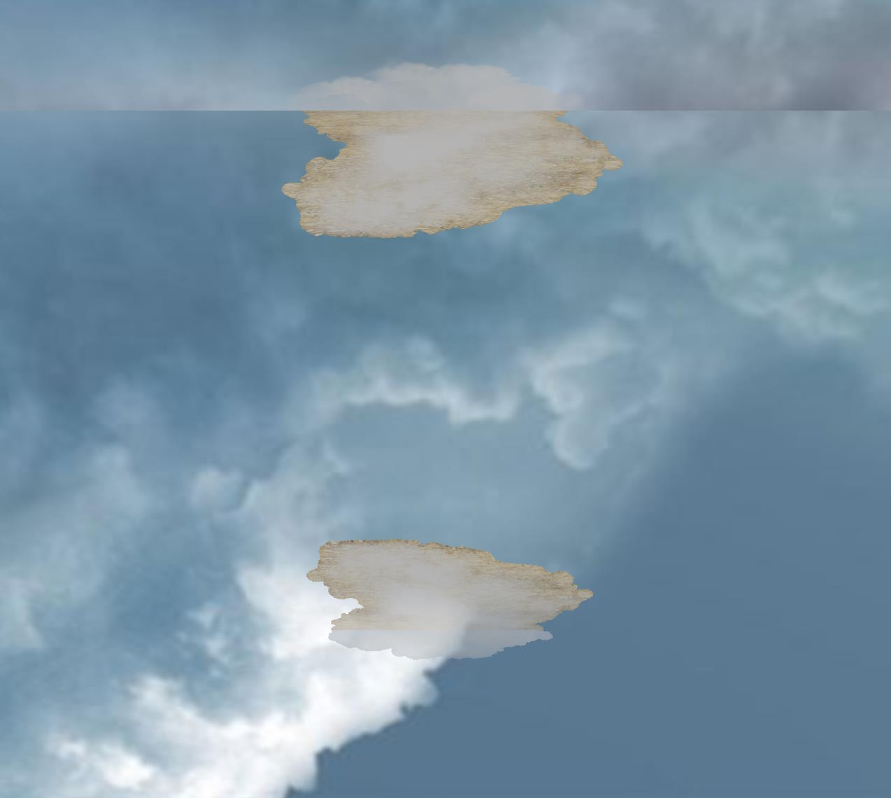
For automatic thickness calculation (enableAutomaticThicknessComputation = true) to work, the back sides must exist, so that a thickness can be accurately calculated by subtracting the depth read from the back and front depth textures. If some of your objects have only front faces, you will get nasty artifacts:
| This plane does not have a back face | Some of the objects of the robot don't have back faces |
|---|---|
This plane does not have a back face 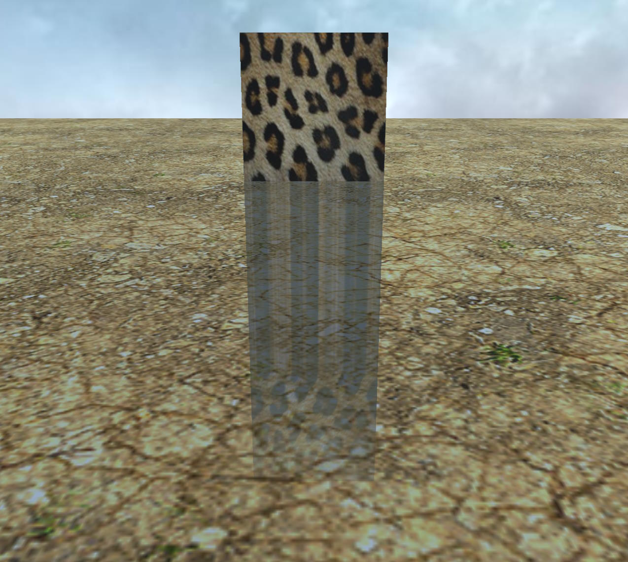 | Some of the objects of the robot don't have back faces 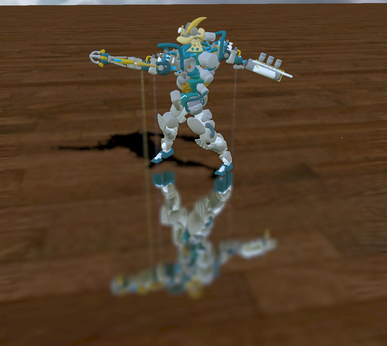 |
The solution is to make sure that all objects have back sides:
- for the plane it's easy, just set
plane.material.backFaceCulling = false - for the robot, it's not so easy, you have to find the defective meshes and either create back faces for them or set
backFaceCulling = falsefor their materials. Another solution would be to simply disable the automatic thickness calculation!
Here is the PG for the plane example: SSR Artifacts (automatic thickness)
Note that there is a special case for transparent meshes. In the standard rendering pass, transparent meshes do not write to the depth buffer, so it will not be possible to calculate a correct thickness for these subjects. It turns out that transparent meshes write to the depth texture when using the geometry/pre-pass renderer, but the backface depth renderer created internally when enabling automatic thickness calculation does not write to the depth texture for transparent materials. You will need to enable writing of depth values for transparent meshes by doing:
ssr.backfaceForceDepthWriteTransparentMeshes = true;Since this is usually what you want, true is the default value for backfaceForceDepthWriteTransparentMeshes.
You will get the same kind of artifacts if you do not:
| Artifacts when using transparent material | Artifacts fixed |
|---|---|
Artifacts when using transparent material 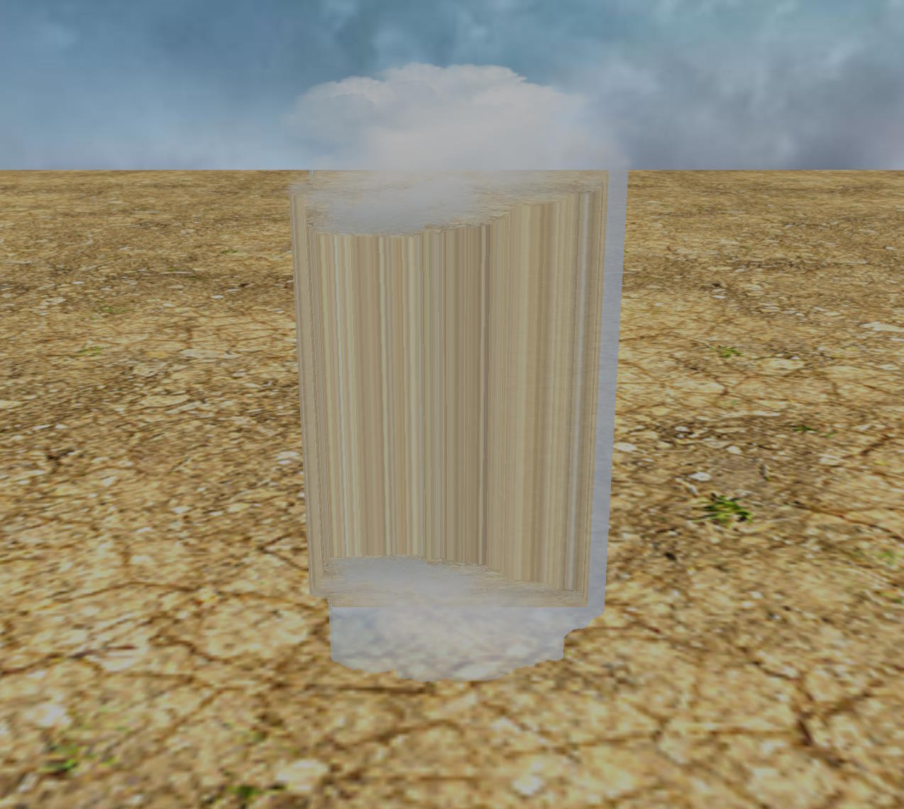 | Artifacts fixed 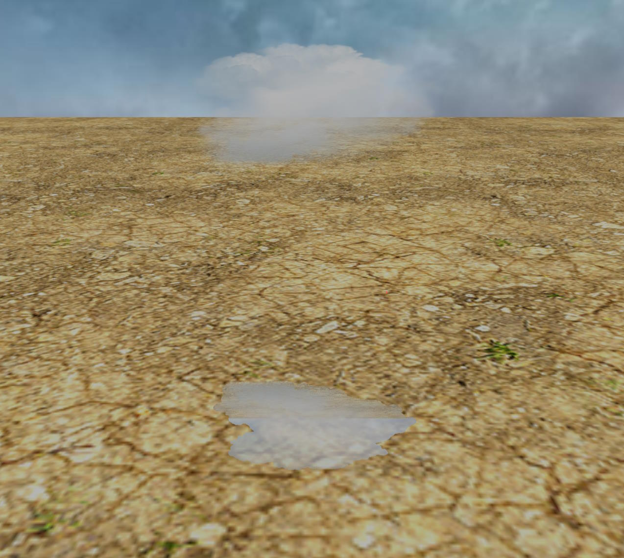 |
Here is the PG corresponding to the screenshot on the right: SSR No Artifacts (automatic thickness transparent meshes)
Artifacts inherent to the SSR technique
Because SSR is a screen-space technique, it can only handle geometry rendered on the screen: when moving, some geometry that was previously visible and reflected on other objects will no longer be visible, and the reflection will disappear when the objects that reflected the geometry are still visible.
Also, the back of the objects cannot be reflected properly, because we only have access to the colors of the front of the objects (the color texture stores what the camera sees, so the front of the objects, not the back).
Attenuate reflections on the edges of the screen
Here's what happens to reflections when geometries go out of view:
The attenuateScreenBorders = true parameter makes the disappearance of reflections less abrupt:
Since this is what you expect by default, true is the default value for attenuateScreenBorders.
Attenuate reflections based on distance
Reflections should be attenuated according to the distance the ray travels before reaching an intersection, and also according to the number of steps we have taken before calculating that intersection. Indeed, if/when we reach the maximum distance/maximum number of steps, we want a smooth transition between what we generated before and after reaching the limit:
Hard transition when maxDistance reached | Hard transition when maxSteps reached |
|---|---|
Hard transition when maxDistance reached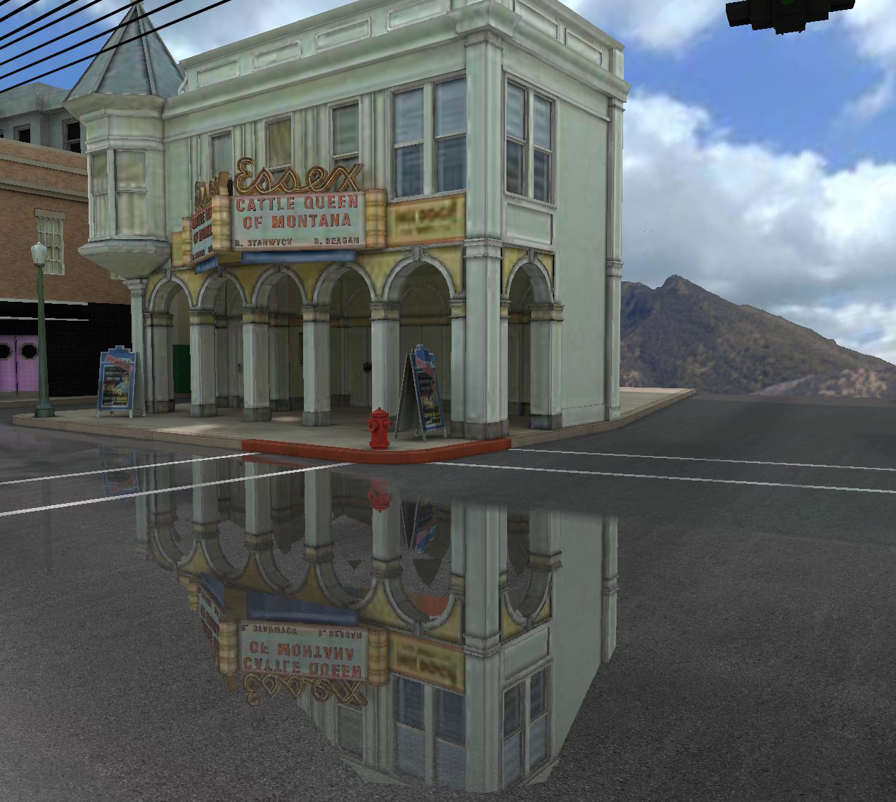 | Hard transition when maxSteps reached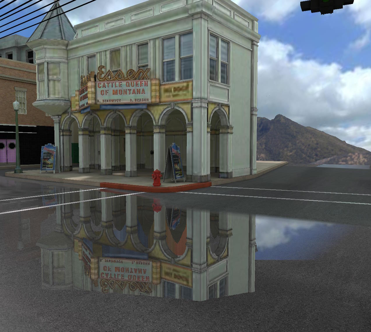 |
If we enable attenuateIntersectionDistance in the first case, and attenuateIntersectionIterations in the second, we get :
Soft transition when maxDistance reached | Soft transition when maxSteps reached |
|---|---|
Soft transition when maxDistance reached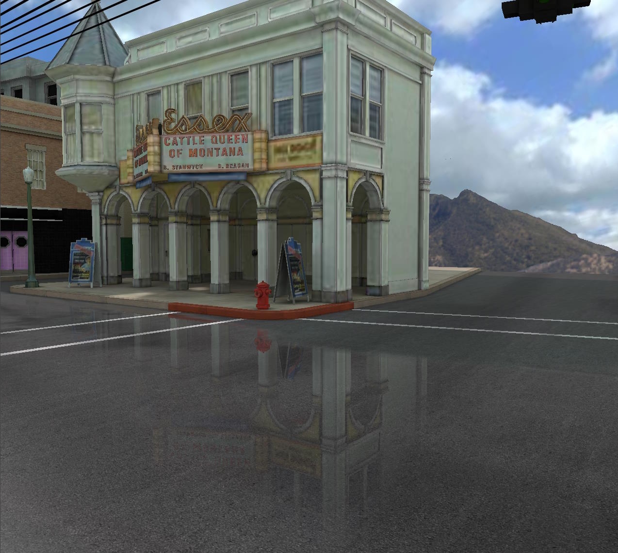 | Soft transition when maxSteps reached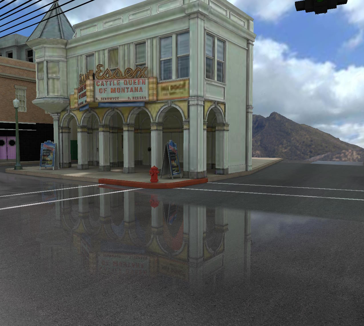 |
This is normally the behavior you want, that's why these two parameters are enabled by default.
Attenuate reflections for rays facing the camera
Reflected rays coming towards the camera should normally be ignored for intersection purposes (by setting attenuateFacingCamera = true), because they will usually hit an object in the back and we only know their colors in the front. However, having a bad reflection can sometimes be better than having no reflection at all, especially if a blur is applied (making the "bad" reflection less obvious):
attenuateFacingCamera = false | attenuateFacingCamera = true |
|---|---|
attenuateFacingCamera = false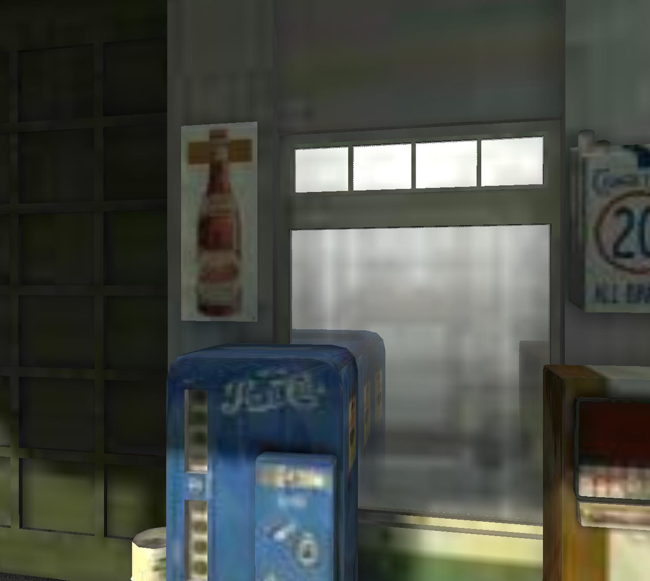 | attenuateFacingCamera = true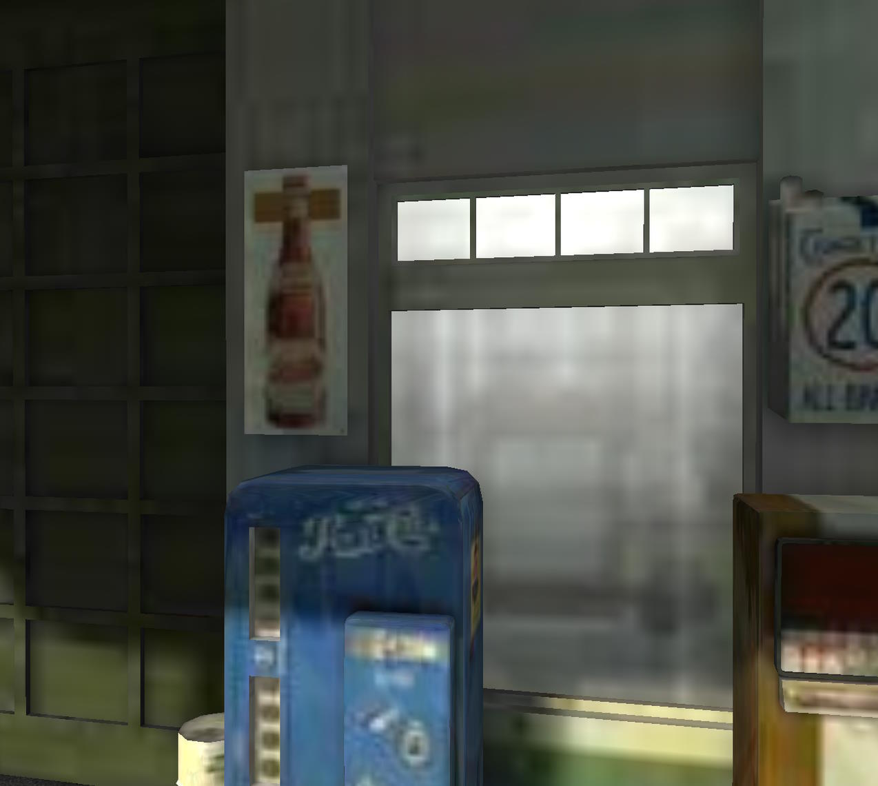 |
As you can see, when the rays facing the camera are not attenuated, we get a "backward" reflection for the gas pumps. These reflections are false because we can't reflect the back of the pumps, but it's not obvious in the screenshot and in the motion + a little blur would probably fool many people! That's why the attenuateFacingCamera parameter is false by default.
Here is the PG corresponding to the screenshot on the left: SSR rays facing camera
Attenuate backface reflections
attenuateBackfaceReflection is used for the same purpose as attenuateFacingCamera and can remove artifacts that the latter cannot. For example
attenuateBackfaceReflection = false | attenuateBackfaceReflection = true |
|---|---|
attenuateBackfaceReflection = false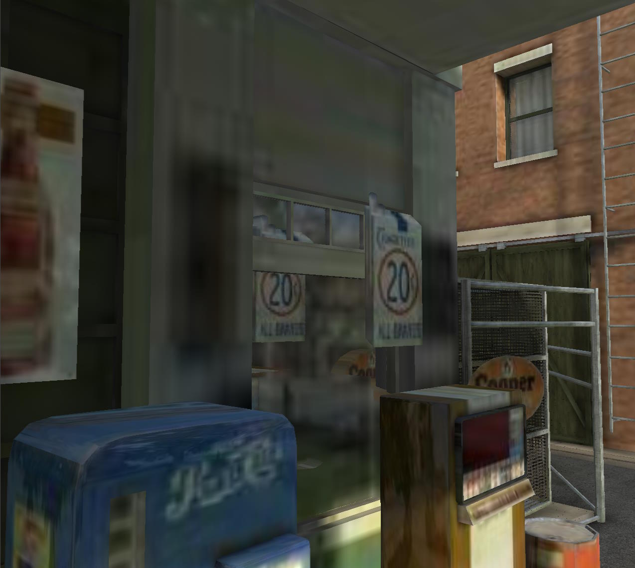 | attenuateBackfaceReflection = true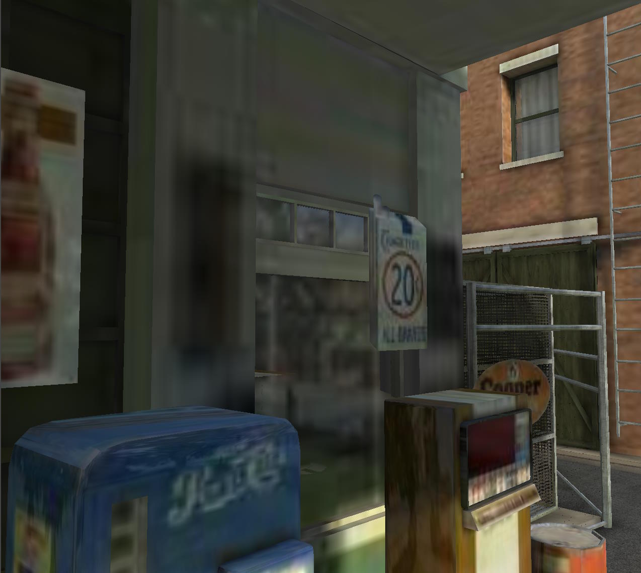 |
The rays reflected from the window that hit the "20" panel make an angle with the direction of the view, which is too large for attenuateFacingCamera to remove the reflections, but attenuateBackfaceReflection is able to do so. This is because it checks the angle between the reflected ray and the normal to the point of intersection, and if they point in the same direction, it attenuates/suppresses the reflections.
Because this check requires additional texture lookup to get the normal to the point of intersection, and also because attenuateFacingCamera can capture most problems, attenuateBackfaceReflection is false by default.
Handling missed intersections
When a reflected ray doesn't hit anything (either because there is no geometry to intersect, or because we have reached the maximum distance / maximum steps), we have two choices for the color we should choose:
- if an environment cube texture has been provided, we read the color from the texture using the direction of the reflected ray
- If no environment texture has been provided, we use the color of the current pixel as a fallback.
If you don't provide an environment texture, you will usually see obvious differences between the pixels for which we were able to find a reflected pixel and those for which we were not:
| No environment texture | Debug view |
|---|---|
No environment texture 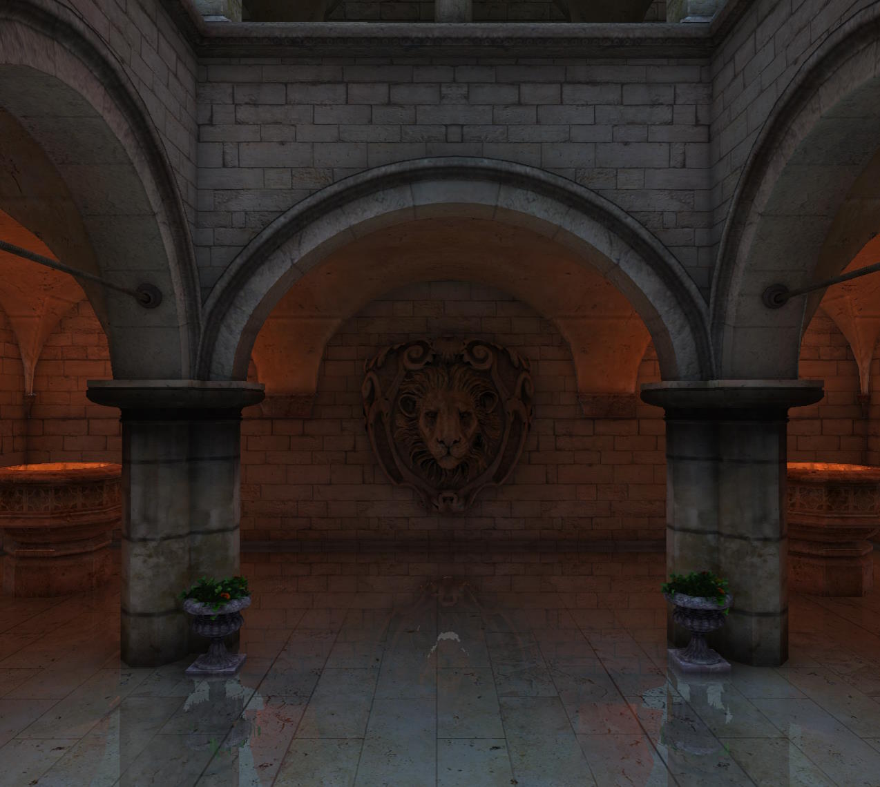 | Debug view 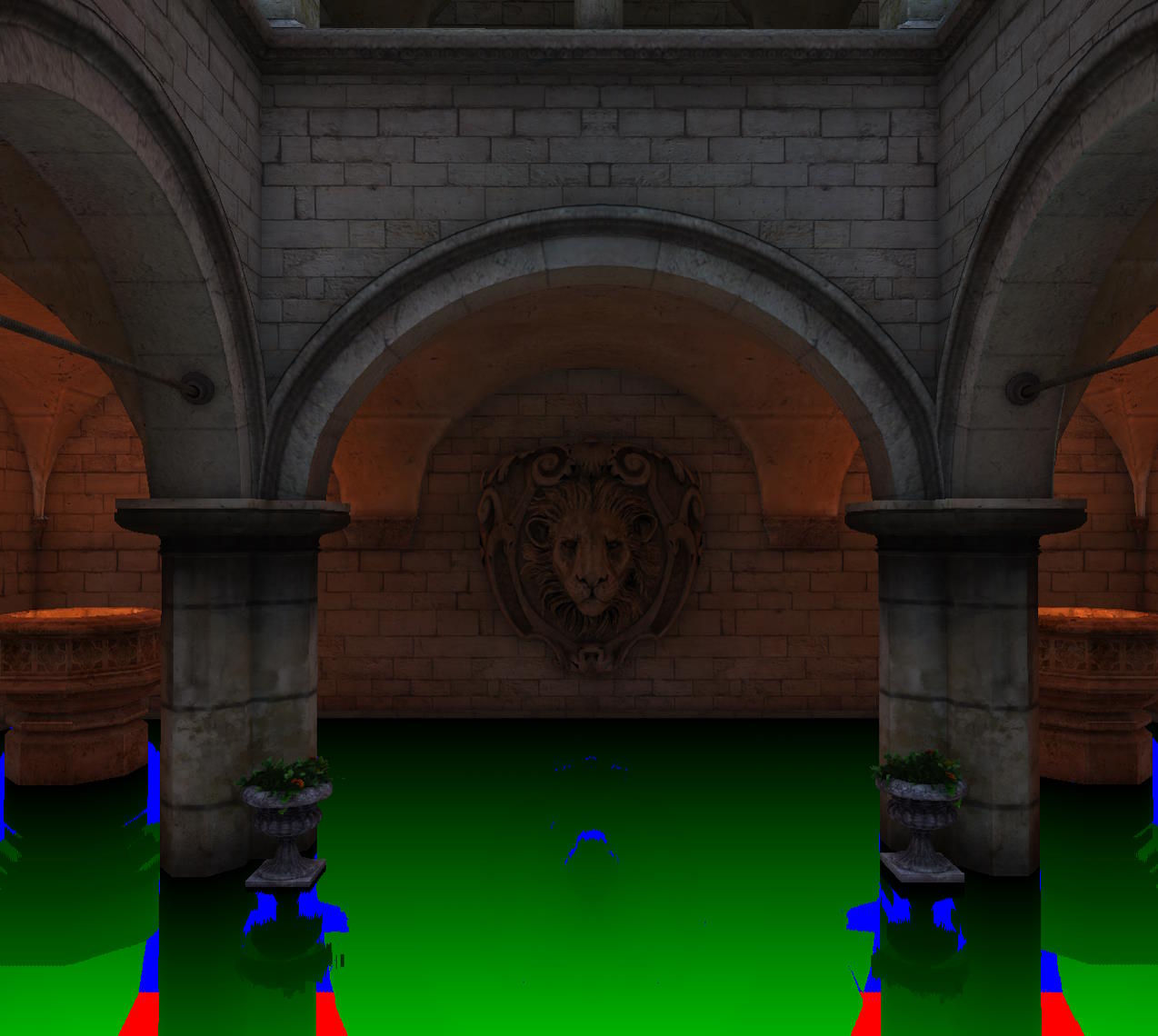 |
The debug view helps to understand what's going on: the lighter pixels on the left screenshot correspond to pixels for which no intersection could be calculated (blue or red on the right screenshot), so we ended up using the original color of the ground for the SSR effect, which is a bit lighter than the pixel that would normally be reflected.
Using an environment texture can help mask these artifacts, as long as the environment texture matches the local environment well! The best way to generate such textures is to use a reflection probe. The probe captures the local environment by rendering the scene as a cube texture from the probe position.
For the screenshot below, a probe was created roughly in the center of the courtyard and was defined as a local cube map by providing a bounding box for the cube, which is roughly the size of the courtyard:
Note that since the environment texture comes from a reflection probe, you need to set ssr.environmentTextureIsProbe to true (a probe cube texture is treated differently than an ordinary cube texture because the Y-axis is reversed).
If you look closely, you will see that some reflections are not quite right, and if you move around, you will see reflections that are clearly misplaced:
One way to mitigate these artifacts would be to use several cube maps, depending on where you are in the scene, and not to use one global cube map for the whole scene.
Here is the PG corresponding to the scene with the local cube map: SSR using local cube map
Managing self-intersections
As explained in How-ssr-is-working, the starting point of the reflected ray is shifted to avoid self-intersections and false reflections. The selfCollisionNumSkip property controls how many iterations to skip at the start before considering an intersection legitimate. While a value of 1 works well in most cases, it is sometimes necessary to increase this value a bit:
selfCollisionNumSkip = 1 | selfCollisionNumSkip = 2 |
|---|---|
selfCollisionNumSkip = 1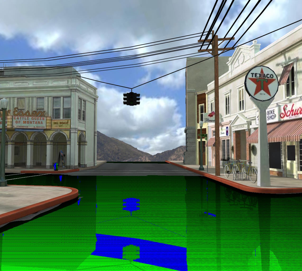 | selfCollisionNumSkip = 2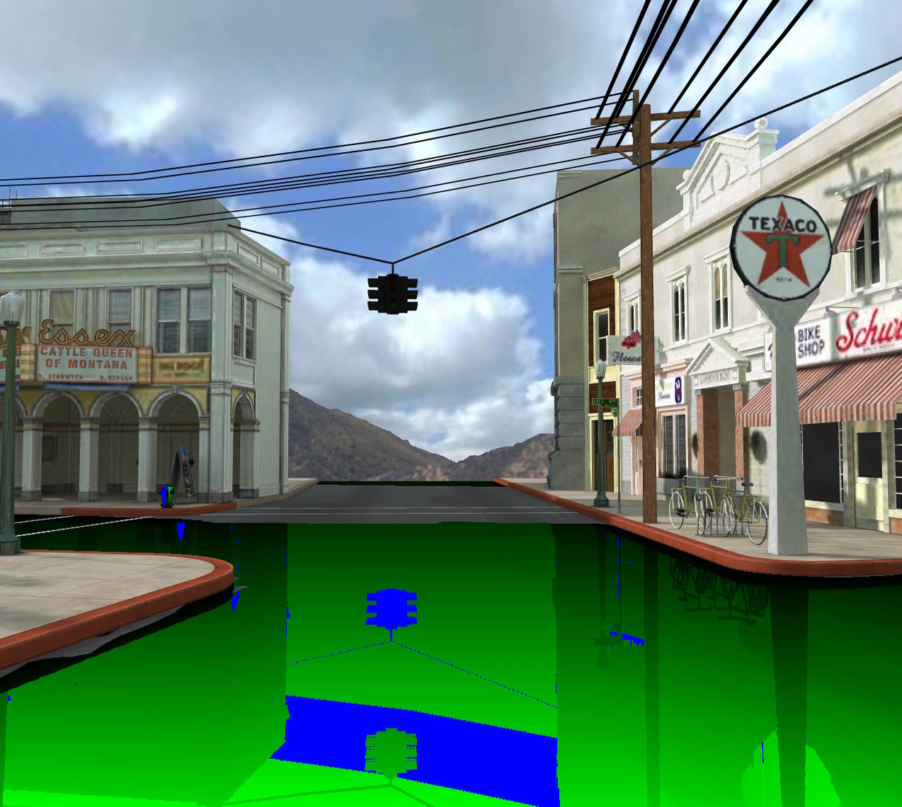 |
Optimize SSR in your scenes
As you can see above, SSR is not a perfect technique (far from it!), and you have to deal with a number of artifacts and limitations. Most of your work will be in trying to hide these artifacts as much as possible, and making sure the effect works as fast as possible within these constraints.
To make the SSR as fast as possible, you should:
- use the largest possible values for
step - use the smallest possible values for
maxStepsandmaxDistance - disable
enableSmoothReflections- but, with larger values ofstep, you may want to enable this setting - disable
enableAutomaticThicknessComputation- this option will render your scene a second time to generate a back depth buffer! - Use values as large as possible for
blurDownsample. - Use as large values as possible for
ssrDownsample. This parameter acts likeblurDownsamplebut for the SSR effect itself. Also, it will only have an effect when the blur is on (so whenblurDispersionStrengthis greater than 0).
Here is a playground demonstrating two different settings for the Hill Valley scene:
SSR (Hill Valley) optimizationFor the starting position (GPU is an RTX 3080Ti, canvas size is 1278x1200):
| Total GPU frame time | GPU time for SSR alone | |
|---|---|---|
| Quality settings | Total GPU frame time 6.6ms | GPU time for SSR alone 4.15ms |
| Optimized settings | Total GPU frame time 1.35ms | GPU time for SSR alone 0.2ms |
In the optimized case, the blur + final merge take 0.05ms, so the full SSR effect takes 0.25ms! For comparison, the same scene without SSR takes 0.9ms. So, in reality, the SSR effect takes 1.35 - 0.9 = 0.45ms and not 0.25ms. The difference between 0.25ms and 0.45ms (0.2ms) is the extra time needed to render normal, depth and reflectivity textures. In the end, the optimized settings are 4.4 / 0.45 ~ 10 times faster than the quality settings!
Of course, the final rendering is not exactly the same in both cases, but as you can see in the PG, it is still quite usable and not that different from the quality settings.
The times shown above are when using the pre-pass renderer. When using the geometry buffer renderer, the times are as follows:
| Total GPU frame time | GPU time for SSR alone | |
|---|---|---|
| Quality settings | Total GPU frame time 8.1ms | GPU time for SSR alone 4.3ms |
| Optimized settings | Total GPU frame time 2.23ms | GPU time for SSR alone 0.2ms |
It is slower because the geometry buffer renderer must perform an additional scene rendering to generate the normal, depth, and reflectivity textures, whereas the pre-pass renderer generates them as part of the normal scene rendering.
Further reading
- http://casual-effects.blogspot.com/2014/08/screen-space-ray-tracing.html
- https://sourceforge.net/p/g3d/code/HEAD/tree/G3D10/data-files/shader/screenSpaceRayTrace.glsl
- https://github.com/kode80/kode80SSR
- https://sakibsaikia.github.io/graphics/2016/12/26/Screen-Space-Reflection-in-Killing-Floor-2.html
- https://github.com/godotengine/godot/blob/master/servers/rendering/renderer_rd/shaders/effects/screen_space_reflection.glsl
- https://doc.babylonjs.com/typedoc/classes/babylon.ssrrenderingpipeline