Planning Mesh UVs for Babylon.js
Why are UVs important?
When planning assets for rendering in Babylon.js, there are several considerations to keep in mind. One of the most critical areas which affects the render quality of the entire scene is the UV layout used by the scene’s meshes. But what are UVs and why are they important? Let us first define some concepts around UVs so that we are all starting from the same point. The UV layout for a mesh is the definition of your 3D object projected into a square 2D mapping. This mapping uses a coordinate system to define which pixel of a material’s texture corresponds to a specific position on a mesh.
Put a different way, the UVs for a mesh are very similar to a sewing pattern for making an article of clothing. The pattern pieces are positioned on the fabric and cut out before sewing them together to make a three-dimensional garment that can be worn. If there is a printed image on the fabric, we can position the pattern pieces to define how that printed image will wrap around the garment. The same happens with mesh UVs. We project the mesh into UV space and then slice it so we can flatten the 3D mesh into two dimensions. Ideally, we do this without stretching UVs out of their original proportions so that there is no distortion on a texture applied to the mesh’s material.
Projecting a Mesh into UV Space
In the below example, we see a 3D cube on the right and the unwrapped UV layout on the left. In this example, we can imagine the cube as a cardboard box that we slice along certain edges to allow it to lay flat. Each vertex in the mesh has a specific coordinate between 0 and 1 on both the U (horizontal) and V (vertical) axes and those coordinates will be written as part of the mesh parameters when saving or exporting the asset.
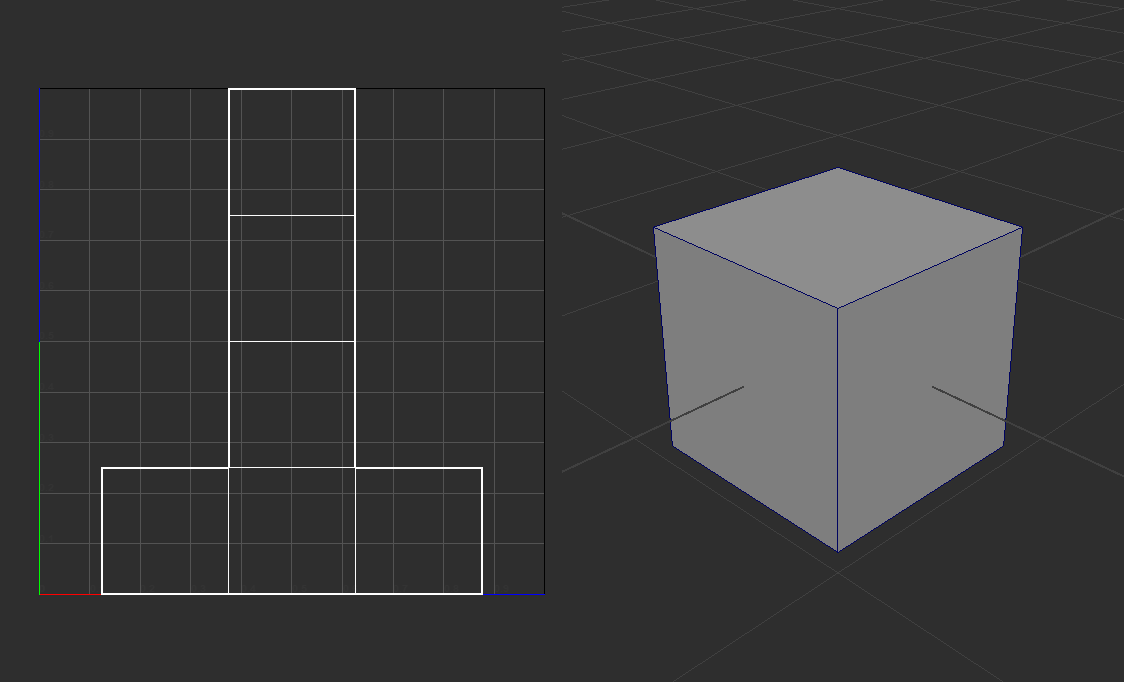
This mapping defines how the pixels of a texture are wrapped around the mesh based on where each mesh UV is located. A group of contiguous UVs are called a UV island. In the example above, there is one UV island describing the layout for the entire mesh. Notice that there are large sections of UV space that are unused in the upper-left and upper-right sections.
Typically, an effective UV layout will utilize as much space as possible, leaving little unused space. This is because any unused space results in wasted data in the texture. Even if the mesh doesn’t reference parts of the texture because the UVs don’t utilize those parts, they still need to be downloaded and retained in memory. This is one way an unoptimized UV layout can hurt the performance of a scene.
The above example shows a typical approach to packing UV islands to maximize the used texture. One thing to note is that there should be some space between UV islands to account for mip mapping. As the engine mip maps a texture, neighboring pixels will average. If the islands are too close, the pixels at the edge of the island may average with pixels of a neighboring island which can cause rendering errors pulling in colors from different parts of the mesh and highlighting mesh seams.
Texture Mapping in UV Space
Using the same cube as above and applying a simple grid texture to the cube’s material illustrates how textures map from UV space to 3D space. We can easily see in this example that the texture is applied with no distortion as each face is projected into UV space retaining the proportions of the face in three-dimensional space as well as the proportion of each face to one another. Typically, the more a mesh is sliced in UV space – into what are called islands – the less distortion will affect the texture when rendered on the mesh surface. The tradeoff here is that more UV islands means more seams in the mesh which could cause difficulties in authoring the texture particularly when using tiling textures. More seams can also lead to artifacts in the render when the texture is mip-mapped which can highlight the seams in the mesh.

Texture Distortion Due to UV Placement
Well projected mesh UVs are important to retain the quality of the applied textures. To easily demonstrate how a texture can be distorted by the UV layout, one of the cube’s UVs was moved to stretch the UV projection in relation to the original face proportions. The effect on the texture is extremely easy to see.
There are times when tiny amounts of stretching in a UV layout are necessary, especially when UV mapping a complex mesh. It is always best to minimize stretching, but sometimes reducing the number of seams in the mesh is worth a small amount of stretching.
UV Seams and Texture Mapping
A simple example of sewing one seam together – the edge between face 2 and 3 – produces an expected distortion to the texture. However, notice that the grid is now continuous between face 2 and 3 where in the other examples, the grid did not line up. There will be times when it is important not to break the flow of the texture as it wraps around the mesh so it is a trade-off between distortions and seams.
Texel Density
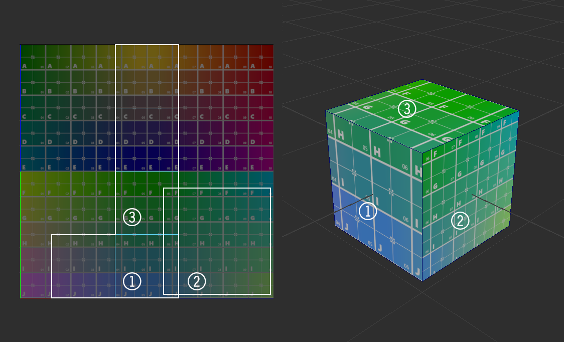
One other concept that is important to understand is how the UV layout affects the resolution of a texture in a mesh’s material. In the image below we see that the face labeled with a 2 has been sliced from the original island and scaled larger in the UV layout.
The number of texture pixels – or texels – an island covers is referred to the texel density. When one of the cube’s faces is enlarged in UV space, the texel density is increased. This effectively increases the resolution of the texture on that face which is obvious from the change in grid size when compared to other faces in the cube.
When speaking of texel density, most often we will need to maintain texel density across a mesh so that no part of the texture looks higher- or lower-quality than the rest. Resolution changes in a texture as it wraps around a mesh produces a jarring effect that is obvious to the viewer. However, there are times when we want to mismatch texel density between islands. One of those would be using a higher texel density on a character’s face than in the lower extremities if the character’s face is close to the camera. In that sense, we are choosing where to put more texture detail into the mesh in the critical areas of the asset.
Overlapping UVs
Another thing to note on the example above is that the two islands that make up the cube UVs in the last example are overlapping. This is completely reasonable to do in certain circumstances as it repeats the same pixels from a texture across multiple places on the mesh. Laying UV islands over one another for parts of the asset that look similar, allows us to save space in our UV layout to maximize texel density. Below is an example of overlapping UVs to increase texel density overall in the asset.
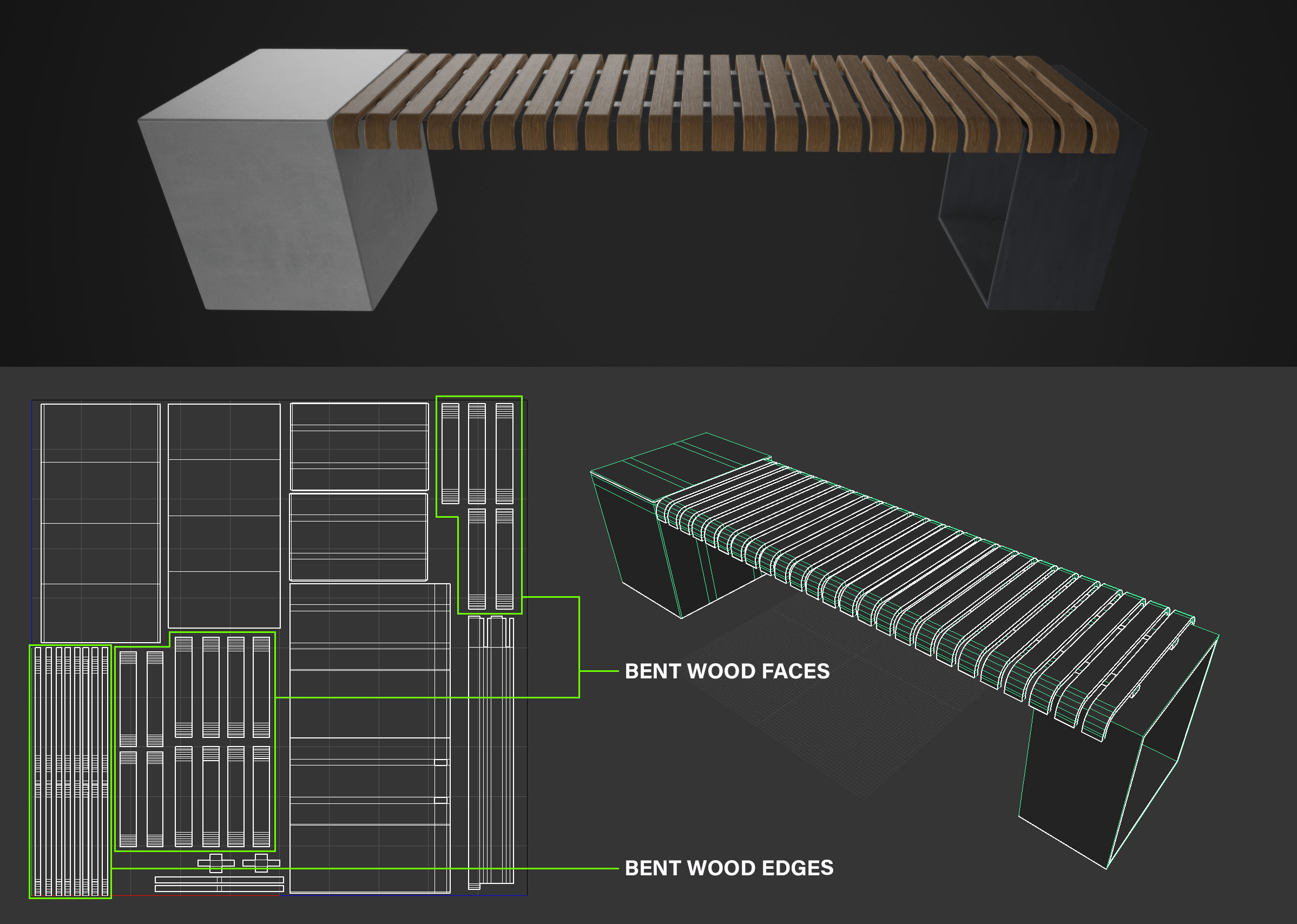
In this case, the bent wood pieces that make up the seat of the bench are the same but need to show some variation in surface pattern to make it feel realistic. If the asset were going to be accurate to the real world, we would need to lay out all four sides (two faces and two edges) of the twenty-five individual bent wood pieces in our UV layout. To fit all these islands in, we would need to make all islands smaller to account for all the needed islands. This means all islands would be using far fewer texels and would lead to the asset looking low quality.
One fix for this is to use a larger texture size. However, this leads to longer downloads and more resources tied up to keep the texture in memory. Another fix is to overlap some of the islands so that while we get some repeating in the wood grain pattern, spreading out the pieces that share the same texture space means our eye won’t pick up on the pattern. This reduces the overall area required in the UV layout for bent wood pieces allowing all islands to be larger and have more texel density.
This kind of technique is common in games to maximize texel density by mirroring UVs on symmetrical models. This is done by deleting all faces for one half of the model, which requires an edge that flows right through the exact center of the model. The remaining faces have their UVs laid out as large as possible in UV space. Then the mesh is mirrored over the center line and all overlapping vertices are merged. The effect in UV space is that the duplicated and mirrored faces retain the exact UVs of the original faces, even though the mesh faces are mirrored. The effect will be that the texture will mirror itself over the center line of the model allowing greater texel density than a unique unwrap. Any signs of mirroring can be minimized by including detail mesh over the seam to break up the pattern of the mirrored pixels.
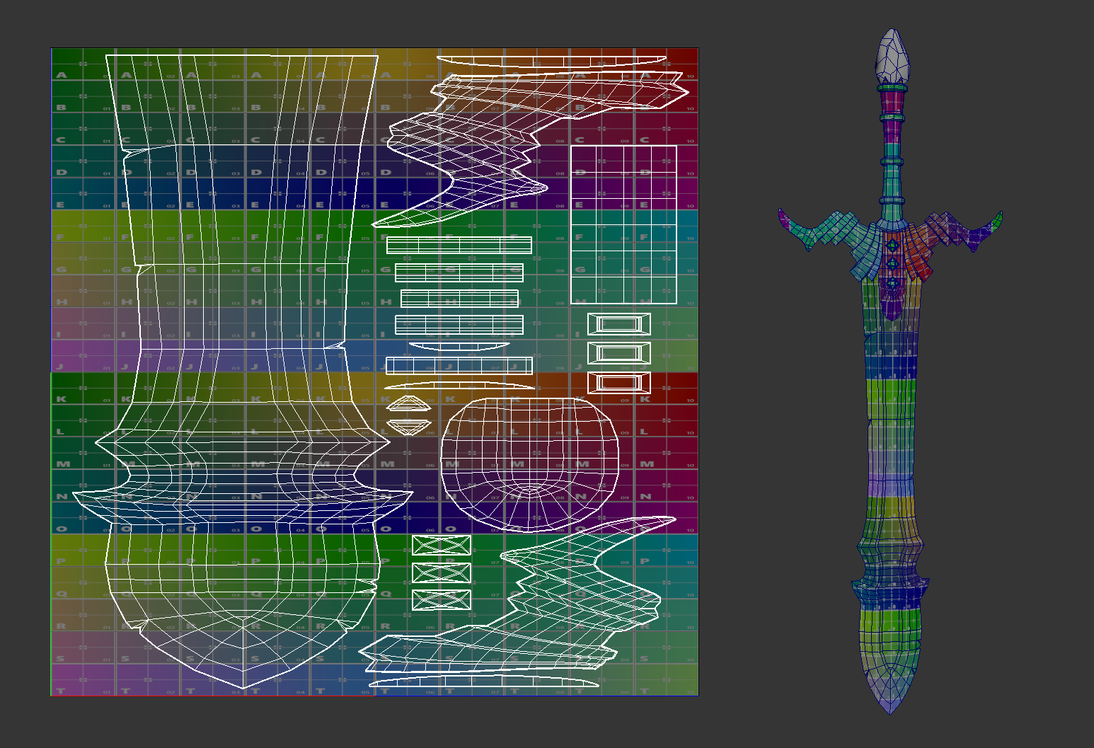
Mirroring of UVs can be seen in the image above. Since the user can normally only see one side of the sword at once, unless they are viewing along the edge, mirroring of UVs can really help increase texel density. If the user notes any mirroring of texture pixels, it means they are looking at the edge of the sword and the hard edge and lighting will help minimize the issue.
This example also shows another concept that is important to keep in mind, which is UVing for non-square textures.
Using Non-Square Textures
There are times when laying out mesh UVs that it becomes obvious that the proportions of the mesh does not utilize the 0-1 UV space effectively. Since Babylon.js does support non-square textures, there are some techniques that can help maximize our texel density. In the example above, the asset is very tall with some contiguous sections that would not be good candidates for seams. If the asset was laid out in a square texture, there would be a lot of wasted texels, even without mirroring UVs.
In this case, using a texture that is twice as tall as wide alleviates the issue. The taller texture offers more texels where they are needed and allows us to keep the long parts of the mesh as a single island. Further adding mirrored UVs allows the islands to get larger and adds even more texel density allowing a high quality render of the textures.
However, UV space still considers 0-1 as the operative space for the texture, meaning that any UVs outside 0-1 space are mapped to the wrap option of the texture – either a repeat of the texture or a clamped value. So even though the asset is using a texture twice as tall as wide, we still need to lay out our islands inside the 0-1 space. One easy way to do this would be to project all UV islands as normal, but then lay them out within the 0-2 space of the textures longest dimension. Then once the layout is final, scale all UVs by 50% in the long dimension and position them all within 0-1 space. This is how the UVs if the sword were created, and leaving the scale to the last step allows us to move and rotate our islands as much as needed to find the best layout before scaling to the final size.
Of course, this technique can work with any proportion of texture and the layout process just needs to take the final proportion of the texture into account.
UVs for Multiple Materials
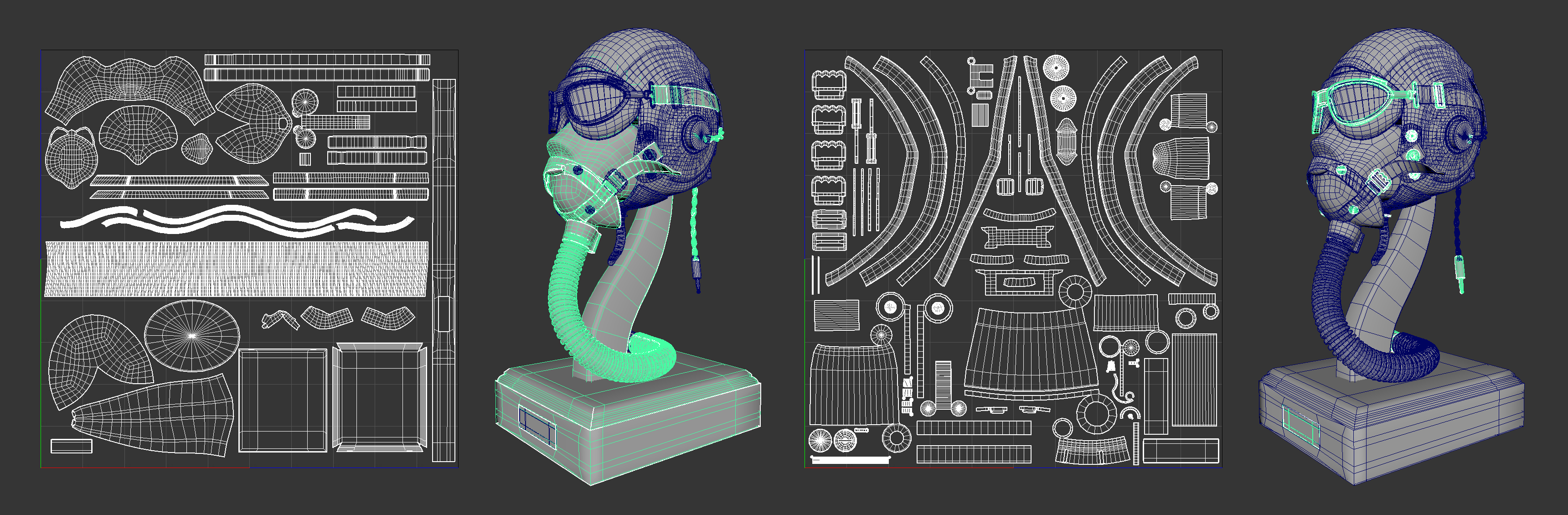
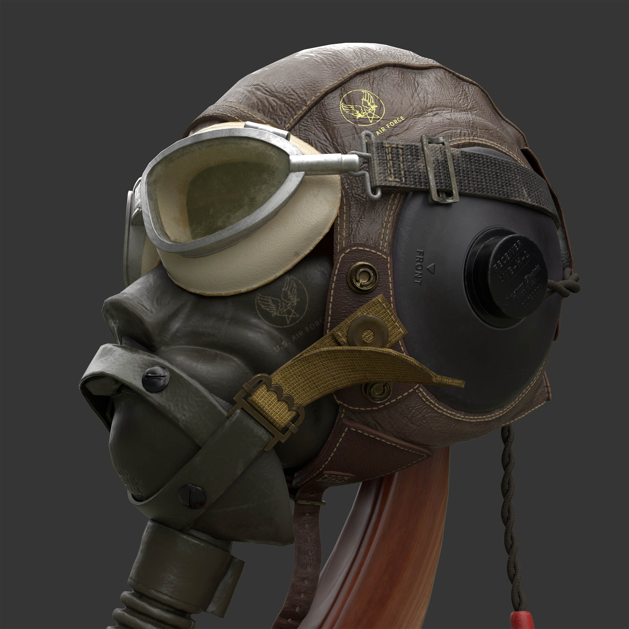
Material breaks can be an effective way to organize UVs. When there are rendering requirements between materials – such as materials that are transmissive versus materials that are opaque – a new UV layout is needed for each material. Only meshes that share a particular material will be considered for a particular UV layout. Referring to the image from earlier, we can see that there are two UV layouts each containing a subsection of meshes from this complex asset. The difference here is that the left layout is for non-metallic parts like wood, plastic, and cloth. The layout on the right is for metallic parts such as clips, snaps, and plugs. By breaking the mesh into multiple materials, we may be able to eliminate a texture like the metallic texture and replace it with a factor in the material parameters. It also allows for a maximizing of texel density as each set of parts has more room in the UV layout.
The tradeoff means we have more draw calls due to the multiple meshes and materials, but in the case of this asset, the camera can get close to the asset and the textures need to be high quality. In this case, the increase in draw calls is worth more texel density on the mesh. Many real time assets will want to keep draw calls to a minimum, but there could be a compelling reason to break a mesh into multiple materials to get a better UV layout. It could even allow for textures of different resolutions assigned to each material to reduce the download and memory footprint of the textures. Ideally, texel density across the asset should be consistent but that doesn’t mean every texture set needs to be the same size.
Atlased UVs
Atlasing for UVs is the practice of layout out each face in a mesh a unique place in UV space. The original cube example and the flight helmet example use atlased UVs. The bench example and the sword example can not be considered atlased since there are mesh faces that share UV space. This distinction is important for specific types of textures like Ambient Occlusion or Lightmap textures. This is because information is baked into the texture and may not bake correctly on shared UVs. In the case of an ambient occlusion texture, dark pixels are baked into areas of concavity and where mesh faces intersect. In the case of light maps, light and/or shadow information is baked into the texture based on where the light strikes the surface.
It's easy to see how faces sharing UV space can be problematic here as you will have information baked based on one face while other faces sharing that UV space may not be lit the same way. In this case you will likely need to make sure your asset is atlased instead of using UV mirroring or overlapping UV islands in any way.
Tiling UVs
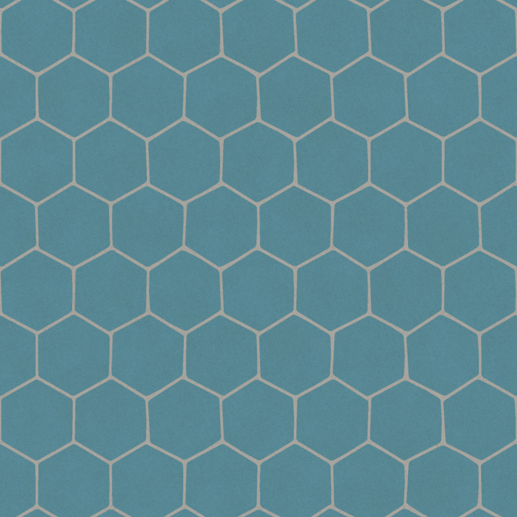
Tiling UVs requires some planning to make use of a tiling texture. A tiling texture will look like the below example where pixels on the left side will align and wrap with pixels on the right as does the top and bottom. This means that when the texture tiles, it will appear as a continuous pattern with no obvious seams.
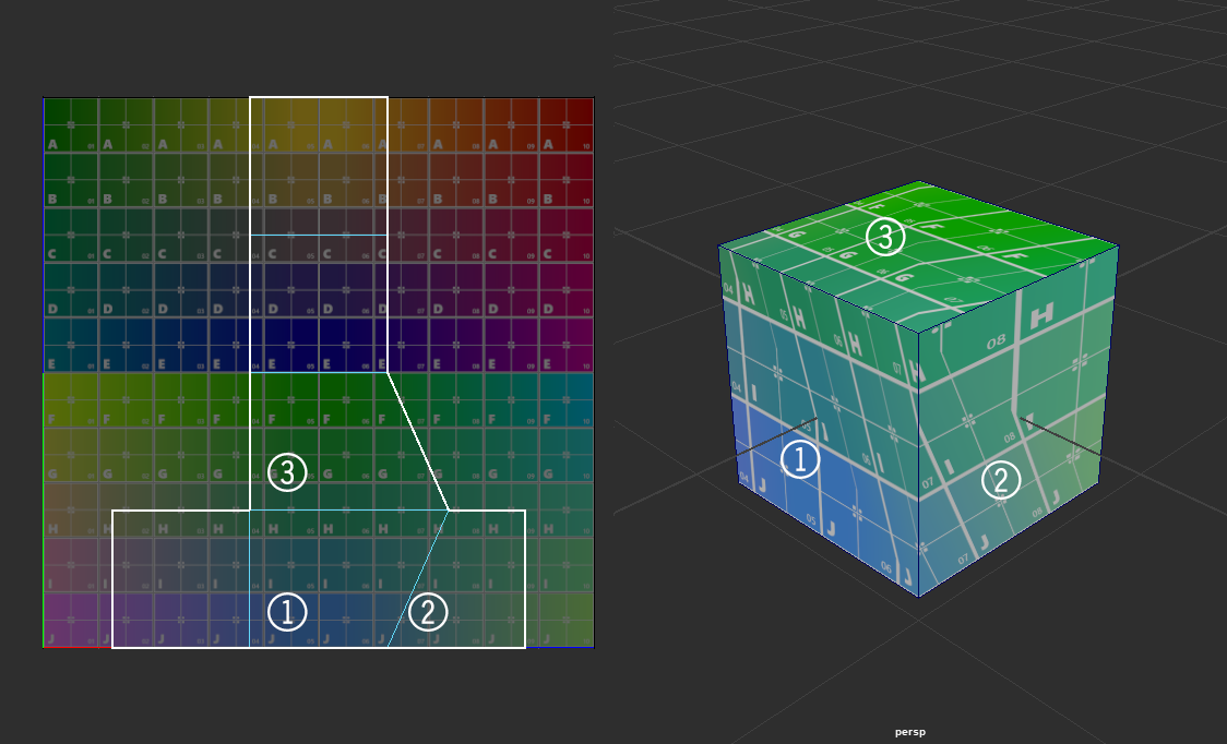
To take advantage of tiling textures, when a mesh is UVed, any seams need to be placed along the edge of UV space in such a way that the texture wraps exactly across the paired edges of a seam. To illustrate this, consider the asset below, which needs to be able to tile but needs a seam right in the middle of one side due to the cylindrical nature of the mesh. Figure 1 shows where the UV seam is placed, indicated by the white edge, which will be easily seen as a camera rotates around the mesh. The UV layout shows that the seams of the UV island are placed along the perimeter of 0-1 space which allows the tiling texture to wrap without any artifacts across the seam.
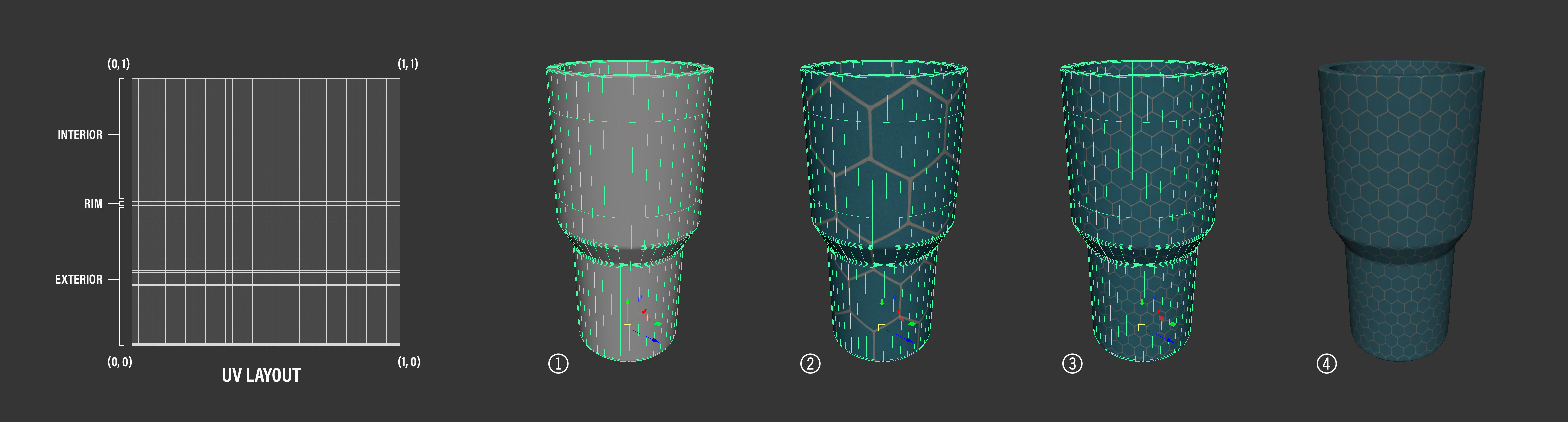
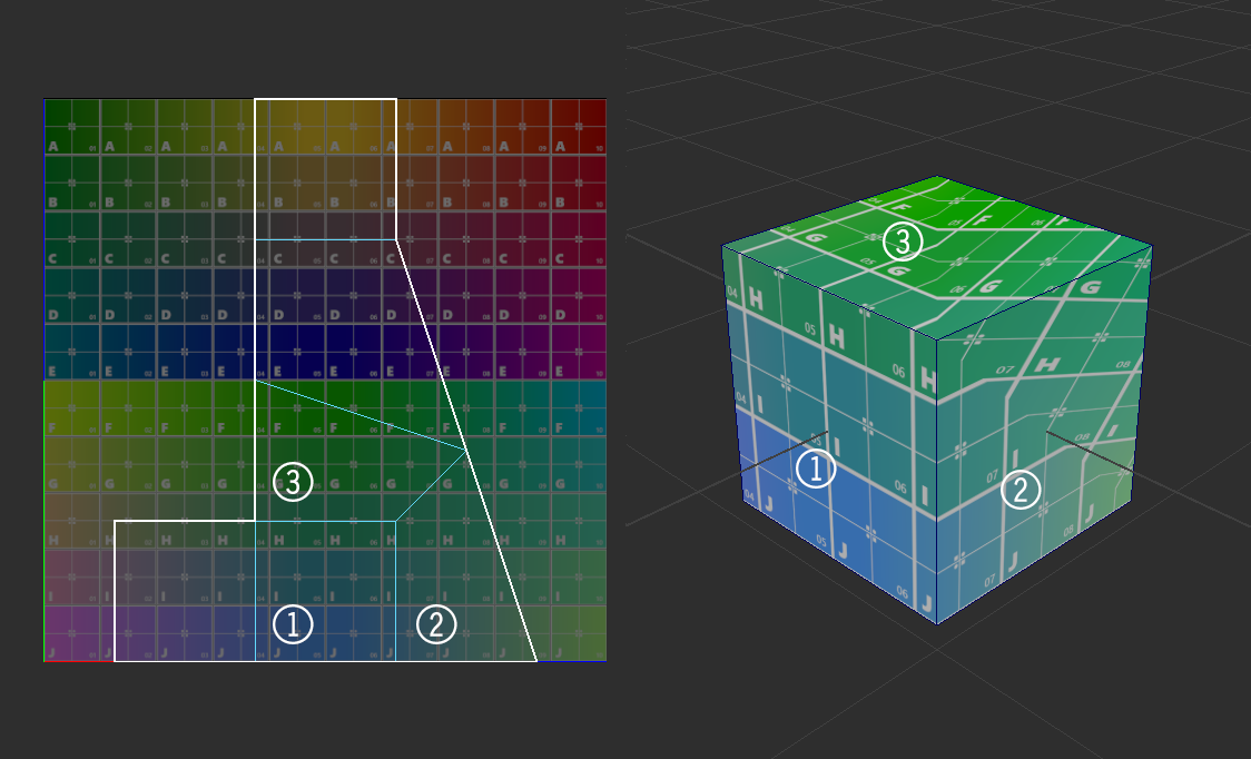
Figure 2 shows the tiling texture example from above wrapping across the UV seam. Note that there are no breaks in the texture and all pixels are displayed on the mesh. Figure 3 shows the same texture with four times the tiling amount as the previous example and Figure 4 shows the tiling texture wrapping the surface without any of the mesh edges highlighted. Note that there are no visible seams on the mesh which is due to laying out he UV islands to use up the entirety of 0-1 UV space.
It is worth noting that the mesh proportions, when unwrapped into the UV layout above, are not square. This means that there is some distortion of the texture which needs to be accounted for in the texture parameters. Setting the V tiling factor to 1.25 accounts for the distortion in the UVs and renders the texture as authored on the mesh.
Obviously, an asset can utilize an atlased UV layout to have full control over the asset’s texture and a unique unwrap, or it can rely on tiling textures to maximize texel density and minimize texture size for assets that need large areas of similar texture. But what if an asset needs to utilize both atlased textures and tiling textures in the same asset? This is where multiple UV sets come into play.
Multiple UV Sets
It is common that assets need to have multiple UV sets to utilize multiple types of textures. It could be that your UV layout utilizes some overlapped islands like the bench asset, but also needs to incorporate an Ambient Occlusion texture. In this case, making a second UV set which atlases the mesh UVs and eliminates overlaps will allow for the baking and rendering of an Ambient Occlusion texture. The texel optimization of the overlapping UV islands in the main texture are lost and so the texel density of the Ambient Occlusion texture will be less than the rest of the textures. However, since the Ambient Occlusion texture is non-color data and meant to block lighting in the crevasses of the asset, a slightly lower texel density may not be as obvious as it would if the lower texel density were present in the base color texture.
Whenever an asset needs to mix methods for unwrapping a mesh, using multiple UV sets becomes crucial. This allows the asset to hold several definitions for UV unwrapping a single mesh and the texture can be assigned to the correct UV set using Texture.coordinatesIndex. This means that even using a single material, each texture can be assigned an individual UV set, so the Ambient Occlusion texture can use a UV set that is altased while the other textures can use a UV set that has overlapping UVs or tiling textures. Babylon.js can define six different UV sets per mesh and they are available in the Texture and Mesh classes as well as in the Node Material Editor on the mesh.uv block.
Lightmap Textures and UVs
Lightmap textures in Babylon.js, like other engines, will require an atlased UV set so that the light and shadow information is baked into a unique portion of the texture for every UV island. If an asset whose materials rely on tiling textures requires a lightmap, a second UV set will need to be created with an atlas of the UV islands. This is the UV set that the lightmap will be baked from and is the UV set that will be assigned to the lightmap texture within Babylon.js.
There are times, however, where multiple asset will be baked into one lightmap. One reason would be to keep the texel density of the lightmap texture consistent across several assets. Obviously, there is a limit as too many assets baked into one lightmap would reduce the quality of the lightmap as the UV islands could become very small and utilize only a very small texel density within the texture. To bake multiple assets into one lightmap, they must all be atlased with one another to create a unique UV layout with no UV islands from any asset overlapping one another.
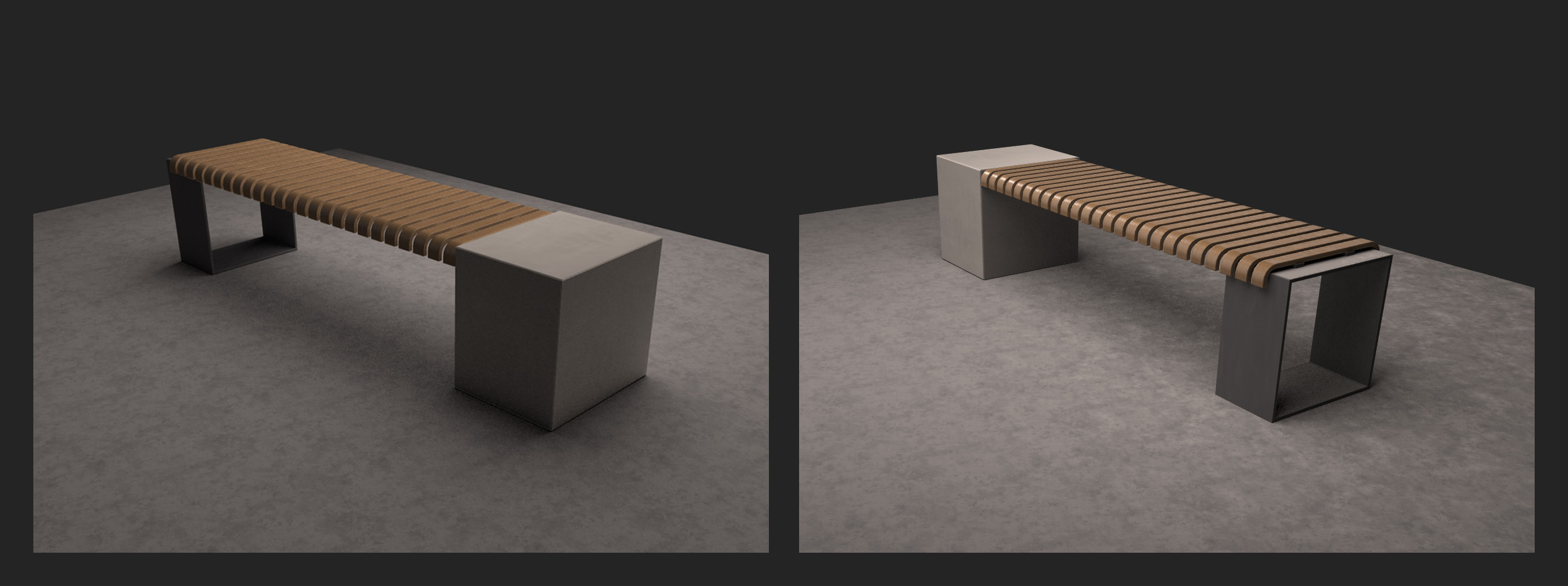
The image below shows the bench asset sitting on a ground plane. The bench and ground each have their own material and UV layout unique to that asset. The bench, as mentioned earlier, does have some islands in its UV layout that overlap to maximize texel density and the ground plane’s UVs are set up to use a tiling texture.
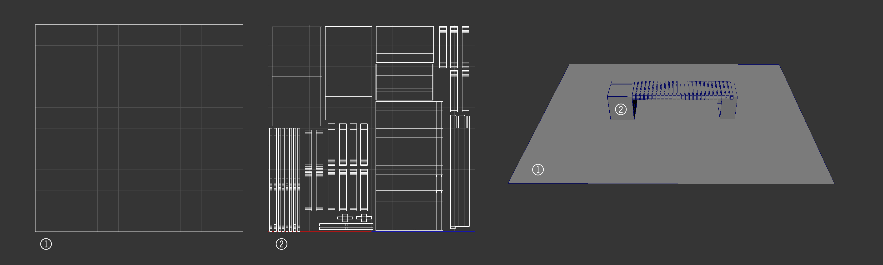
If we want to bake a lightmap texture for these assets, the ground would be ok as it has no overlapping UV islands. The bench would need a new UV set with a unique unwrap to make sure no islands overlapped. However, if we want to bake one lightmap texture that both assets can reference to maintain texel density between the assets, we need a new unwrap that contains both meshes.
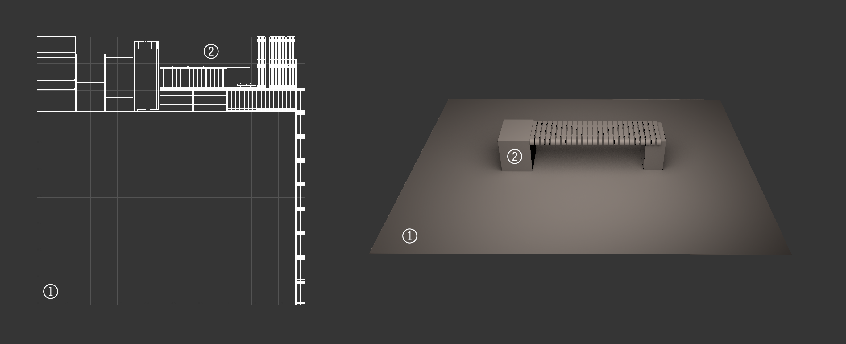
In this new unwrap, the ground plane and the bench asset’s UV islands are scaled so they all have the same texel density in UV space. Then they are arranged into one unique layout with the ground UVs in the lower left and the bench UVs stacked around the edges of the ground UVs. On the right is the baked texture applied to the asset to illustrate the lightmap data and how it is using the second UV set.
In the final Babylon.js renders above, the lightmap texture is combined with the PBR textures to give a more realistic shadow on the assets. In this case, we assign the lightmap texture to the second UV set and the lightmap texture is tagged to be used as a shadowmap.
The method of baking out a lightmap texture is dependent on which digital content creation (DCC) tool is being used. Layout out the UVs for baking, though, should be the same for any DCC tool. The thing to remember is that whenever light and shadow data is baked from a mesh to a texture, the unwrap should be atlased and unique to ensure that light and shadow render where they are supposed to and not show up in incorrect areas due to overlapping UV islands.
Last Thoughts
There are many problems that can be solved just by how a mesh’s UVs are laid out. Utilizing UV techniques that serve the asset’s needs can help maximize the quality of the asset’s textures as well as optimize the asset for download and render. Experimenting with the UV layout of an asset can often lead to better results. However, it should be noted that changing the UV layout for an asset after textures have been created can be costly if the textures were created by hand. It is less costly if the textures are created through a non-destructive or procedural process, but the textures will need to be rebuilt with the new UV layout and that can create new problems based on how much the UV layout has changed.
Planning for an asset’s need early in production will often hint at what the UV layout will have to handle. Using UV grid textures for the early stages of asset creation can help determine texel density and consistency or help plan where to apply a higher texel density within an asset. And understanding the capabilities of Babylon.js which can handle non-square and non-power-of-two textures, among other things, can offer new avenues of optimizing or increasing an asset’s render quality.