Node Geometry Editor Nodes
What to Expect
This page is a breakdown of each node available in the Node Geometry Editor. The nodes will be listed in the same order by group as they are in the tool's node list. The reason for this order is that there may be some generalities that apply to all nodes in a group and those will be listed once rather than repeating them for each node. For each node we will discuss all inputs, outputs, properties, and considerations to ensure all requirements for using a node are highlighted.
Sources
Source nodes are a requirement for any Node Geometry graph as they supply the Geometry that is needed by the GeometryOutput node for the graph to be able to build. Most of these nodes will come with multiple inputs that will set the basic properties of the Geometry, but all have exactly one output which is Geometry generated by the source node.
Each parameter that can be set for the source Geometry can either be set by connecting a node or nodes to set a specific value or it can be set in the properties of the node. If a parameter's port on the node is connected by a wire, the parameter is removed from the parameter list on the node as it is deriving its value from the connected node(s).
If there is a set of connected properties - such as size, width, height, and depth - the more specific properties take precedence over the more general properties. In other words, if values are passed to size AND width then the parameter passed to width will apply to the width of the Geometry and height and depth will take their values from size. In this way, it is normal to see values wired to both general and specific properties at the same time. If, however, there are values passed to size, width, height, and depth then the value passed to size is not used at all and is not needed.
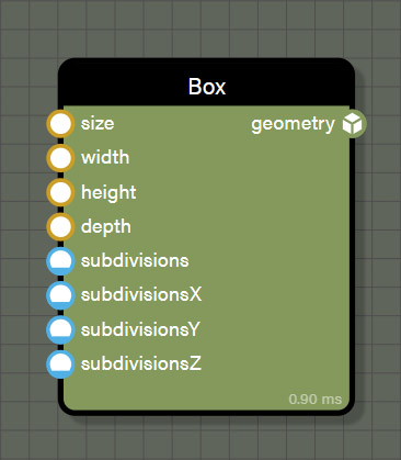
Box
This source node creates a box to the dimensions given at the resolution set by subdivisions as follows.
Inputs
- size is the value used for width, depth, and height of the box.
- width sets the width of the box and overrides any value in size.
- height sets the height of the box and overrides any value in size.
- depth sets the depth of the box and overrides any value in size.
- subdivisions sets the resolution in X, Y, and Z for the box.
- subdivisionsX sets the resolution in X for the box and overrides any value set in subdivisions.
- subdivisionsY sets the resolution in Y for the box and overrides any value set in subdivisions.
- subdivisionsZ sets the resolution in Z for the box and overrides any value set in subdivisions.
Outputs
- geometry is the generated box and fulfills the requirement for at least one geometry in the graph.
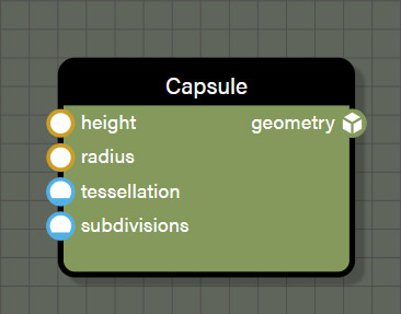
Capsule
This source node creates a capsule to the dimensions given at the resolution set by tessellation and subdivisions as follows.
Inputs
- height sets the height of the capsule from tip to tip.
- radius sets the radius of the capsule.
- tesselation sets the resolution along the circumference of the capsule.
- subdivisions sets the resolution for the height of the capsule between the hemispherical caps.
Outputs
- geometry is the generated capsule and fulfills the requirement for at least one geometry in the graph.
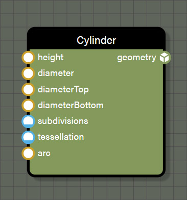
Cylinder
This source node creates a cylinder to the dimensions given at the resolution set by tessellation and subdivisions. It can be created as a complete cylinder, or a partial cylinder as follows.
Inputs
- height sets the height of the cylinder from cap to cap.
- diameter sets the diameter of the cylinder.
- diameterTop sets the diameter of the top cap of the cylinder.
- diameterBottom sets the diameter of the bottom cap cylinder.
- subdivisions sets the resolution for the height of the cylinder between the caps.
- tessellation sets the resolution along the circumference of the cylinder.
- arc is the revolution of the cylinder using the above properties on a 0-1 scale.
Outputs
- geometry is the generated cylinder and fulfills the requirement for at least one geometry in the graph.
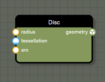
Disc
This source node creates a disc using the given radius the resolution set by tessellation. It can be created as a complete disc, or a partial disc as follows.
Inputs
- radius sets the radius of the disc.
- tessellation sets the resolution of the disc.
- arc is the revolution of the disc using the above properties on a 0-1 scale.
Outputs
- geometry is the generated disc and fulfills the requirement for at least one geometry in the graph.
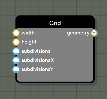
Grid
This source node creates a 2D grid to the dimensions given at the resolution set by subdivisions as follows.
Inputs
- width sets the width of the grid.
- height sets the height of the grid.
- subdivisions sets the resolution in X and Y for the grid.
- subdivisionsX sets the resolution in X for the grid and overrides any value set in subdivisions.
- subdivisionsY sets the resolution in Y for the grid and overrides any value set in subdivisions.
Outputs
- geometry is the generated grid and fulfills the requirement for at least one geometry in the graph.
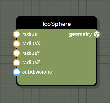
Icosphere
This source node creates an icosphere at the radius given and the resolution set by subdivisions as follows.
Inputs
- radius sets the radius for the X, Y, and Z axes of the icosphere.
- radiusX sets the radius for the X axis of the icosphere.
- radiusY sets the radius for the Y axis of the icosphere.
- radiusZ sets the radius for the Z axis of the icosphere.
- subdivisions sets the resolution for the icosphere.
Outputs
- geometry is the generated icosphere and fulfills the requirement for at least one geometry in the graph.
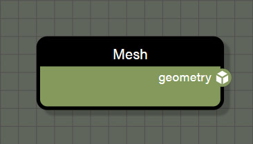
Mesh
This source node holds a mesh loaded from disk or attached from the scene. This node has no inputs because all properties come from the loaded mesh. Meshes can be assigned to this node by using NodeGeometry.getBlockByName("meshBlockName").mesh. Once a mesh is loaded into the node, it will behave like any other geometry source.
Outputs
- geometry is the loaded mesh and fulfills the requirement for at least one geometry in the graph.
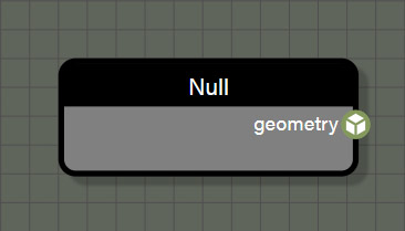
Null
This source node is empty and adds a null to the geometry flow. This node is used mainly to add some randomness when instantiating geometry on another geometry source by randomly instantiating null geometry. This null does not render anything and is free in terms of calculations which makes it excellent at adding randomness to the geometry flow.
Outputs
- geometry is null, but still fulfills the requirement for at least one geometry in the graph.
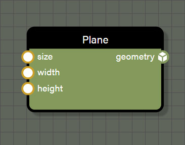
Plane
This source node creates a plane to the dimensions given as follows. The plane is created with exactly one subdivision, no more. If control over subdivisions is desired, use Grid instead.
Inputs
- size is the value used for width and height of the plane.
- width sets the width of the plane and overrides any value in size.
- height sets the height of the plane and overrides any value in size.
Outputs
- geometry is the generated plane and fulfills the requirement for at least one geometry in the graph.
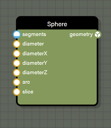
Sphere
This source node creates a sphere of the given diameter at the resolution set by segments. It can be created as a complete or a partial sphere as follows.
Inputs
- segments sets the resolution of the sphere.
- diameter is the value used for diameter of the X, Y, and Z axes of the sphere.
- diameterX sets the diameter of the sphere's X axis and overrides any value in diameter.
- diameterY sets the diameter of the sphere's Y axis and overrides any value in diameter.
- diameterZ sets the diameter of the sphere's Z axis and overrides any value in diameter.
- arc is the revolution of the sphere on the Y axis on a 0-1 scale.
- slice removes loops from the bottom of the sphere upward on a 0-1 scale.
Outputs
- geometry is the generated sphere and fulfills the requirement for at least one geometry in the graph.
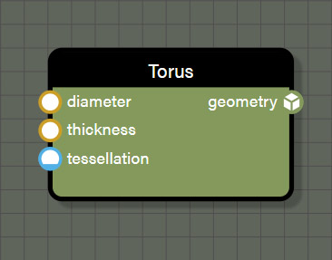
Torus
This source node creates a torus of the given diameter at the resolution set by tessellation as follows.
Inputs
- diameter sets the diameter of the ring of the torus.
- thickness sets the diameter of the circle defining the thickness of the torus.
- tessellation sets the resolution for the torus both in diameter and thickness.
Outputs
- geometry is the generated torus and fulfills the requirement for at least one geometry in the graph.
Inputs
Input nodes consist of basic value types used to set properties on other nodes. There are a few common properties on all input nodes. Those consist of the following.
- Mode allows the input to be defined as a user-defined value or a contextual value of any type. User-defined values are just as they seem, the user assigned a constant value to the node. A contextual value is derived from the closest geometry node associated with this node. Changing mode to a different value can also change the type of data the node represents. For example, a Float input can be changed to a Vector2 contextual value which will change the data type supplied by the node. Be aware of this when changing mode as it can affect connections to other nodes. Note that if mode is set to a contextual value, the node will no longer display Visible on frame, Min, Max, or Value in the node properties but will instead display Contextual value.
- Contextual value assigns the source of the data for any input set to a contextual value. The sources available depend on the data type selected for the input node. For example, choosing a Int contextual value allows access to vertex IDs and choosing a Vector3 contextual value would offer vertex positions.
- Visible on frame is a boolean which allows any input contained within a frame to be visible in the INPUTS list of the properties panel for a frame. Simply enable the boolean and then whenever a frame is selected - expanded or collapsed - any visible input can have its value changed directly in the frame properties panel.

Float
This input node represents a Float value rounded to four decimal places. The node contains the following properties which can be set in the properties panel.
Properties
- Min provides the minimum value and if set, the node will create a slider between minimum and maximum values. For the slider to work correctly, ensure that the Min value is lower than Max value.
- Max provides the maximum value and if set, the node will create a slider between minimum and maximum values. For the slider to work correctly, ensure that the Max value is higher than Min value.
- Value is a user defined value that is either an input field or a combination of input field and slider if Min and Max are set. The value set in the field will be rounded to four decimal places by default.
Outputs
- value is the Float value set on the node.
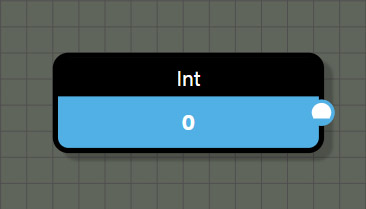
Int
This input node represents an integer value and contains the following properties which can be set in the properties panel.
Properties
- Min provides the minimum value and if set, the node will create a slider between minimum and maximum values. For the slider to work correctly, ensure that the Min value is lower than Max value.
- Max provides the maximum value and if set, the node will create a slider between minimum and maximum values. For the slider to work correctly, ensure that the Max value is higher than Min value.
- Value is a user defined value that is either an input field or a combination of input field and slider if Min and Max are set. If a Float value is entered, any fractional value after the decimal will be ignored.
Outputs
- value is the integer value set on the node.
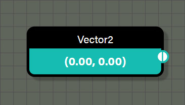
Vector2
This input node represents a Vector2 value and contains the following properties which can be set in the properties panel.
Properties
- Value displays the value set in the node. To change the value, click on the plus (+) icon to get the input fields for each channel. These values are rounded to three decimal places by default though the node only displays two decimal places.
Outputs
- value is the Vector2 value set on the node.
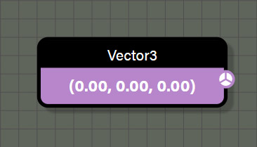
Vector3
This input node represents a Vector3 value and contains the following properties which can be set in the properties panel.
Properties
- Value displays the value set in the node. To change the value, click on the plus (+) icon to get the input fields for each channel. These values are rounded to three decimal places by default though the node only displays two decimal places.
Outputs
- value is the Vector3 value set on the node.
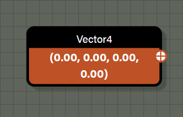
Vector4
This input node represents a Vector4 value and contains the following properties which can be set in the properties panel.
Properties
- Value displays the value set in the node. To change the value, click on the plus (+) icon to get the input fields for each channel. These values are rounded to three decimal places by default though the node only displays two decimal places.
Outputs
- value is the Vector4 value set on the node.
Contextual
Contextual nodes consist of values derived from the closest source associated with a contextual node in the graph. The way to determine what source is referenced by a contextual value is to trace wires from the contextual value node until finding a node that has a reference that could supply the context. For contextual nodes that reference geometric values like position or normal, trace wires to the first node that references geometry, and this will be the source that is being referenced.
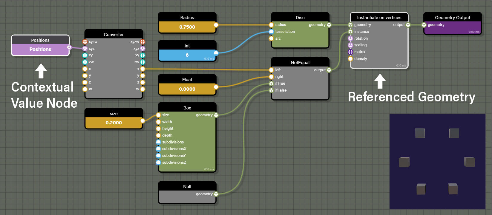
In addition to geometric contextual values, there are other types of contextual values. One of them being LoopID which is a contextual value for the iteration of a node that loops. In this case, tracing wires to the first node that is iterable would be the source for the contextual value.
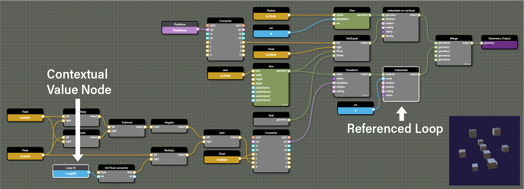
To help in identifying what source is feeding a contextual value, the graph will highlight the node providing the source of the contextual value when selecting any contextual value as can be seen in the images above. The playground below can be used to experiment with contextual values and better understand how they reference their source.
Contextual nodes are typically an array of values determined by the components of the source such as the vertices of referenced geometry or There are a couple of common properties on all input nodes. Those consist of the following.
- Mode allows the node to be defined as a user-defined value or a contextual value of any type. User-defined values are just as they seem, the user assigned a constant value to the node. A contextual value is derived from the closest geometry node associated with this node. Changing mode to a different value can also change the type of data the node represents. For example, a CollectionID contextual node can be updated to a Vector2 contextual value which will change the data type supplied by the node. Be aware of this when changing mode as it can affect connections to other nodes. Note that if mode is changed to user-defined, the node will no longer display Contextual value but will instead show Visible on frame, Min, Max, and Value in the node properties.
- Contextual value assigns the source of the data for any input set to a contextual value. The sources available depend on the data type selected for the input node. For example, choosing a Int contextual value allows access to vertex IDs and choosing a Vector3 contextual value would offer vertex positions.
CollectionID
This contextual node represents the ID of a source geometry in a collection. This data is pulled from geometry associated with a collection node.
Outputs
- value is an integer representing the Collection ID of an associated geometry.

Colors
This contextual node represents an array of vertex colors from a source geometry. This data is pulled from geometry associated with this contextual node through a connection to a shared node.
Outputs
- value is a Vector4 representing the colors of each vertex of an associated geometry.

FaceID
This contextual node represents an array of the IDs for each face of a source geometry. This data is pulled from geometry associated with this contextual node through a connection to a shared node.
Outputs
- value is an integer representing the IDs for each face of an associated geometry.

GeometryID
This contextual node represents the ID for a source geometry. This data is pulled from geometry associated with this contextual node through a connection to a shared node.
Outputs
- value is an integer representing the ID for associated geometry.

LoopID
This contextual node represents the ID of the loop iteration of an associated node with a count input like the Instantiate node. This node can be used to increment values such as those driving the transform of the translation, rotation, or scale of an associated geometry being instantiated through a loop. This data is pulled from an iterable node associated with this contextual node through a connection to a shared node.
Outputs
- value is an integer representing the ID of the iteration of the associated loop.
Normals
This contextual node represents an array of vertex normals from a source geometry. This data is pulled from geometry associated with this contextual node through a connection to a shared node.
Outputs
- value is a Vector3 value representing the normals of each vertex of an associated geometry.
Positions
This contextual node represents an array of vertex positions from a source geometry. This data is pulled from geometry associated with this contextual node through a connection to a shared node.
Outputs
- value is a Vector3 value representing the positions of each vertex of an associated geometry.
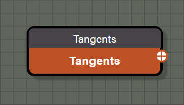
Tangents
This contextual node represents an array of vertex tangents from a source geometry. This data is pulled from geometry associated with this contextual node through a connection to a shared node.
Outputs
- value is a Vector4 value representing the tangents of each vertex of an associated geometry.
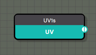
UVs
This contextual node is actually six different nodes, each one representing an array of UV coordinates for each vertex from a particular UV set from a source geometry. Each node represents a different UV set of the six supported UV sets for a mesh in Babylon.js. This data is pulled from geometry associated with this contextual node through a connection to a shared node.
Outputs
- value is a Vector2 value representing the UV coordinates of each vertex of an associated geometry.
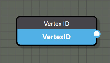
VertexID
This contextual node represents an array of vertex IDs from a source geometry. This data is pulled from geometry associated with this contextual node through a connection to a shared node.
Outputs
- value is an integer representing the ID of each vertex of an associated geometry.
Logical
Logical nodes are used to branch a node graph by performing a test between two Float values. If the test between the two values meets the condition set by the node, a value of true is returned and the nodes connected to the ifTrue port are passed to the output. Otherwise, the nodes connected to the ifFalse port are passed to the output. There are common properties that are possessed by all logical nodes and are as follows.
- right is an input field to be able to set a Float value for the right port manually. This is a shortcut to help reduce complexity on the graph if the test needs to be done against a constant value.
- Test sets the condition for the comparison between the two values connected to the node. Any logical can be easily changed to another logical node simply by changing the Test parameter without needing to replace the node with a different logical node.
- ifTrue and ifFalse ports on each logical node do not need to be connected to anything for the node to function. If a node is connected to ifTrue or ifFalse, that node will be passed when appropriate condition is met. If nothing is connected to ifTrue or ifFalse, the node will output 1.0 and 0.0 respectively. This allows for successive logical tests by testing if the previous logical test was true (1.0) or false (0.0) without the need to wire Float nodes for ifTrue and ifFalse in the graph.

And
This logical node tests if the Float value in the left port and the right port are both not equal to 0.0. If the test returns true, the value of ifTrue is passed otherwise the value of ifFalse is passed.
Inputs
- left is connected to a node providing a Float value to be used in the test.
- right can be connected to a node providing a Float value to be used in the test or a constant value can be set in the input field of the properties panel for this node.
- ifTrue can be connected to any data type including geometry but needs to be the same data type as connected to ifFalse and will determine the data type for the output port on this node. If nothing is connected, the value assumed by ifTrue is 1.0.
- ifFalse can be connected to any data type including geometry but needs to be the same data type as connected to ifTrue and will determine the data type for the output port on this node. If nothing is connected, the value assumed by ifFalse is 0.0.
Outputs
- output is the value attached to ifTrue if the test returns true or the value attached to ifFalse if the test returns false. If one or both ports for ifTrue and ifFalse are not connected, the output passes 1.0 if the test returns true and 0.0 if the test returns false.
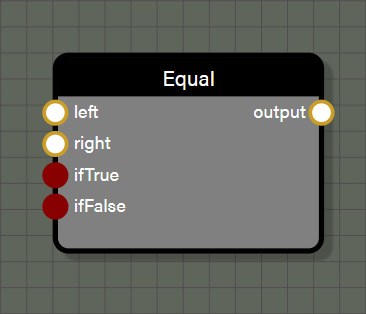
Equal
This logical node tests if the Float value in the left port and the right port are both equal to one another. If the test returns true, the value of ifTrue is passed otherwise the value of ifFalse is passed.
Inputs
- left is connected to a node providing a Float value to be used in the test.
- right can be connected to a node providing a Float value to be used in the test or a constant value can be set in the input field of the properties panel for this node.
- ifTrue can be connected to any data type including geometry but needs to be the same data type as connected to ifFalse and will determine the data type for the output port on this node. If nothing is connected, the value assumed by ifTrue is 1.0.
- ifFalse can be connected to any data type including geometry but needs to be the same data type as connected to ifTrue and will determine the data type for the output port on this node. If nothing is connected, the value assumed by ifFalse is 0.0.
Outputs
- output is the value attached to ifTrue if the test returns true or the value attached to ifFalse if the test returns false. If one or both ports for ifTrue and ifFalse are not connected, the output passes 1.0 if the test returns true and 0.0 if the test returns false.
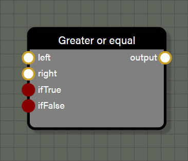
GreaterOrEqual
This logical node tests if the Float value in the left port is greater than or equal to the Floating point value in the right port. If the test returns true, the value of ifTrue is passed otherwise the value of ifFalse is passed.
Inputs
- left is connected to a node providing a Float value to be used in the test.
- right can be connected to a node providing a Float value to be used in the test or a constant value can be set in the input field of the properties panel for this node.
- ifTrue can be connected to any data type including geometry but needs to be the same data type as connected to ifFalse and will determine the data type for the output port on this node. If nothing is connected, the value assumed by ifTrue is 1.0.
- ifFalse can be connected to any data type including geometry but needs to be the same data type as connected to ifTrue and will determine the data type for the output port on this node. If nothing is connected, the value assumed by ifFalse is 0.0.
Outputs
- output is the value attached to ifTrue if the test returns true or the value attached to ifFalse if the test returns false. If one or both ports for ifTrue and ifFalse are not connected, the output passes 1.0 if the test returns true and 0.0 if the test returns false.

GreaterThan
This logical node tests if the Float value in the left port is greater than the Floating point value in the right port. If the test returns true, the value of ifTrue is passed otherwise the value of ifFalse is passed.
Inputs
- left is connected to a node providing a Float value to be used in the test.
- right can be connected to a node providing a Float value to be used in the test or a constant value can be set in the input field of the properties panel for this node.
- ifTrue can be connected to any data type including geometry but needs to be the same data type as connected to ifFalse and will determine the data type for the output port on this node. If nothing is connected, the value assumed by ifTrue is 1.0.
- ifFalse can be connected to any data type including geometry but needs to be the same data type as connected to ifTrue and will determine the data type for the output port on this node. If nothing is connected, the value assumed by ifFalse is 0.0.
Outputs
- output is the value attached to ifTrue if the test returns true or the value attached to ifFalse if the test returns false. If one or both ports for ifTrue and ifFalse are not connected, the output passes 1.0 if the test returns true and 0.0 if the test returns false.

LessOrEqual
This logical node tests if the Float value in the left port is less than or equal to the Floating point value in the right port. If the test returns true, the value of ifTrue is passed otherwise the value of ifFalse is passed.
Inputs
- left is connected to a node providing a Float value to be used in the test.
- right can be connected to a node providing a Float value to be used in the test or a constant value can be set in the input field of the properties panel for this node.
- ifTrue can be connected to any data type including geometry but needs to be the same data type as connected to ifFalse and will determine the data type for the output port on this node. If nothing is connected, the value assumed by ifTrue is 1.0.
- ifFalse can be connected to any data type including geometry but needs to be the same data type as connected to ifTrue and will determine the data type for the output port on this node. If nothing is connected, the value assumed by ifFalse is 0.0.
Outputs
- output is the value attached to ifTrue if the test returns true or the value attached to ifFalse if the test returns false. If one or both ports for ifTrue and ifFalse are not connected, the output passes 1.0 if the test returns true and 0.0 if the test returns false.

LessThan
This logical node tests if the Float value in the left port is less than the Floating point value in the right port. If the test returns true, the value of ifTrue is passed otherwise the value of ifFalse is passed.
Inputs
- left is connected to a node providing a Float value to be used in the test.
- right can be connected to a node providing a Float value to be used in the test or a constant value can be set in the input field of the properties panel for this node.
- ifTrue can be connected to any data type including geometry but needs to be the same data type as connected to ifFalse and will determine the data type for the output port on this node. If nothing is connected, the value assumed by ifTrue is 1.0.
- ifFalse can be connected to any data type including geometry but needs to be the same data type as connected to ifTrue and will determine the data type for the output port on this node. If nothing is connected, the value assumed by ifFalse is 0.0.
Outputs
- output is the value attached to ifTrue if the test returns true or the value attached to ifFalse if the test returns false. If one or both ports for ifTrue and ifFalse are not connected, the output passes 1.0 if the test returns true and 0.0 if the test returns false.

NotEqual
This logical node tests if the Float value in the left port is not equal to the Floating point value in the right port. If the test returns true, the value of ifTrue is passed otherwise the value of ifFalse is passed.
Inputs
- left is connected to a node providing a Float value to be used in the test.
- right can be connected to a node providing a Float value to be used in the test or a constant value can be set in the input field of the properties panel for this node.
- ifTrue can be connected to any data type including geometry but needs to be the same data type as connected to ifFalse and will determine the data type for the output port on this node. If nothing is connected, the value assumed by ifTrue is 1.0.
- ifFalse can be connected to any data type including geometry but needs to be the same data type as connected to ifTrue and will determine the data type for the output port on this node. If nothing is connected, the value assumed by ifFalse is 0.0.
Outputs
- output is the value attached to ifTrue if the test returns true or the value attached to ifFalse if the test returns false. If one or both ports for ifTrue and ifFalse are not connected, the output passes 1.0 if the test returns true and 0.0 if the test returns false.

Or
This logical node tests if either the left port or the right port contain a Floating point value not equal to 0.0. If the test returns true, the value of ifTrue is passed otherwise the value of ifFalse is passed.
Inputs
- left is connected to a node providing a Float value to be used in the test.
- right can be connected to a node providing a Float value to be used in the test or a constant value can be set in the input field of the properties panel for this node.
- ifTrue can be connected to any data type including geometry but needs to be the same data type as connected to ifFalse and will determine the data type for the output port on this node. If nothing is connected, the value assumed by ifTrue is 1.0.
- ifFalse can be connected to any data type including geometry but needs to be the same data type as connected to ifTrue and will determine the data type for the output port on this node. If nothing is connected, the value assumed by ifFalse is 0.0.
Outputs
- output is the value attached to ifTrue if the test returns true or the value attached to ifFalse if the test returns false. If one or both ports for ifTrue and ifFalse are not connected, the output passes 1.0 if the test returns true and 0.0 if the test returns false.
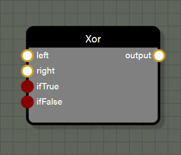
Xor
This logical node tests for an exclusive or so that if either the left port or the right port contains a Float value not equal to 0.0 the test returns true. However, if both the left and right ports contain Float values not equal to 0.0 the test returns false. Only one of the two ports may contain a value not equal to 0.0 to test as true. If the test returns true, the value of ifTrue is passed otherwise the value of ifFalse is passed.
Inputs
- left is connected to a node providing a Float value to be used in the test.
- right can be connected to a node providing a Float value to be used in the test or a constant value can be set in the input field of the properties panel for this node.
- ifTrue can be connected to any data type including geometry but needs to be the same data type as connected to ifFalse and will determine the data type for the output port on this node. If nothing is connected, the value assumed by ifTrue is 1.0.
- ifFalse can be connected to any data type including geometry but needs to be the same data type as connected to ifTrue and will determine the data type for the output port on this node. If nothing is connected, the value assumed by ifFalse is 0.0.
Outputs
- output is the value attached to ifTrue if the test returns true or the value attached to ifFalse if the test returns false. If one or both ports for ifTrue and ifFalse are not connected, the output passes 1.0 if the test returns true and 0.0 if the test returns false.
Math: Standard
These nodes are simple mathematical operations like add, subtract, min, max, or round. The nodes in this section are some of the most used nodes in any of our node graph tools. They are very straight forward, but many of the nodes in this set have features that are worth calling out specifically.

Add
This is a simple math node which adds two inputs together. This node can support Float, Int, Vector2, Vector3, and Vector4 types, though the node cannot add mixed types. The type of the node first connected to an input determines the type for the node output.
Properties
- Operation allows this node to be changed to one of the following operations: Add, Subtract, Multiply, Divide, Min, or Max.
Inputs
- left is connected to a node providing the first value to be used in the operation.
- right is connected to a node providing the second value to be used in the operation.
Outputs
- output is the sum of the left and right inputs and matches type with the values connected to left and right.
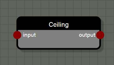
Ceiling
This is a simple function which transforms the input to the smallest whole number that is greater than or equal to the input. This node can support Float, Int, Vector2, Vector3, and Vector4 types. The type for the node connected to the input of this node determines the type for the node output.
Properties
- Operation allows this node to be changed to one of the following functions: Cos, Sin, Abs, Exp, Round, Floor, Ceiling, Sqrt, Log, Tan, ArcTan, ArcCos, ArcSin, Sign, Negate, OneMinus, Reciprocal, ToDegrees, or ToRadians.
Inputs
- input is connected to a node providing a value to be used in the function.
Outputs
- output is the transformed value from the input and matches type with the value connected to input.
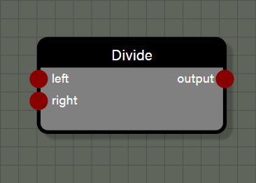
Divide
This is a simple math node which divides the left input by the right input. This node can support Float, Int, Vector2, Vector3, and Vector4 types, though the node cannot divide mixed types. The type of the node first connected to an input determines the type for the node output.
Properties
- Operation allows this node to be changed to one of the following operations: Add, Subtract, Multiply, Divide, Min, or Max.
Inputs
- left is connected to a node providing the first value to be used in the operation.
- right is connected to a node providing the second value to be used in the operation.
Outputs
- output is the quotient of the left input divided by the right input and matches type with the values connected to left and right.

Floor
This is a simple function which transforms the input to the largest whole number that is less than or equal to the input. This node can support Float, Int, Vector2, Vector3, and Vector4 types. The type for the node connected to the input of this node determines the type for the node output.
Properties
- Operation allows this node to be changed to one of the following functions: Cos, Sin, Abs, Exp, Round, Floor, Ceiling, Sqrt, Log, Tan, ArcTan, ArcCos, ArcSin, Sign, Negate, OneMinus, Reciprocal, ToDegrees, or ToRadians.
Inputs
- input is connected to a node providing a value to be used in the function.
Outputs
- output is the transformed value from the input and matches type with the value connected to input.
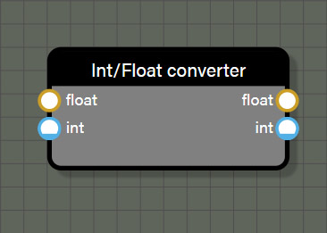
IntFloatConverter
This is a simple function which converts the input type to either a Float or an integer. This node uses specific data types and does not allow connection to nodes that are not defined as Float or Int. While the node appears to allow connections to both the Float and Int inputs, the node will only use the first value connected if more than one is present. In the case of this node, if both inputs are connected, the outputs will both use the input connected to Float for the value to convert.
Inputs
- float is connected to a node providing a Float value to be converted.
- int is connected to a node providing an Int value to be converted.
Outputs
- float is the value from the first input connected to the node transformed to type Float.
- int is the value from the first input connected to the node transformed to type Int.
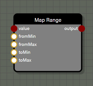
MapRange
This is a simple function to remap a value in relation to one numerical range to a corresponding value in relation to another numerical range. There is no stipulation that the value be within the original numerical range to remap it. This node accepts values that are type Float, Int, Vector2, Vector3, or Vector4.
Inputs
- value is the value whose relation to the original value range is converted to a corresponding value in relation to a new numerical range.
- fromMin is the lower value of the original value range.
- fromMax is the upper value of the original value range.
- toMin is the lower value of the target value range.
- toMax is the upper value of the target value range.
Outputs
- output is the value of the input converted into the target range in a type that matches the input value.

Max
This is a simple math node which returns the larger value between the left input and the right input. This node can support Float, Int, Vector2, Vector3, and Vector4 types, though the node cannot evaluate mixed types. The type of the node first connected to an input determines the type for the node output.
Properties
- Operation allows this node to be changed to one of the following operations: Add, Subtract, Multiply, Divide, Min, or Max.
Inputs
- left is connected to a node providing the first value to be used in the evaluation.
- right is connected to a node providing the second value to be used in the evaluation.
Outputs
- output is the larger value between the left input and the right input and matches type with the values connected to left and right.

Min
This is a simple math node which returns the smaller value between the left input and the right input. This node can support Float, Int, Vector2, Vector3, and Vector4 types, though the node cannot evaluate mixed types. The type of the node first connected to an input determines the type for the node output.
Properties
- Operation allows this node to be changed to one of the following operations: Add, Subtract, Multiply, Divide, Min, or Max.
Inputs
- left is connected to a node providing the first value to be used in the evaluation.
- right is connected to a node providing the second value to be used in the evaluation.
Outputs
- output is the smaller value between the left input and the right input and matches type with the values connected to left and right.
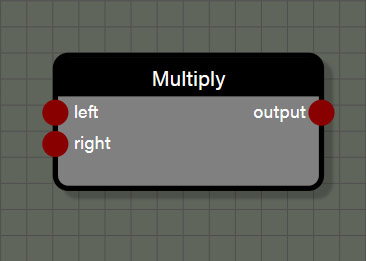
Multiply
This is a simple math node which multiplies the left input and the right input. This node can support Float, Int, Vector2, Vector3, and Vector4 types, though this node is a little different than other nodes that require matching types between left and right inputs. This node can also act as a scale node where a Vector is scaled by a scalar value of type Float. To do this, first connect a Vector to the left input which will set the type for the output port. Second connect a Float to the right input of the node which will act as the scalar. This is the only math node where input types can be mixed, and these mixed input types need to be connected in one specific way. Remember, the left input can take any type and the right input can either take a matching type to multiply normally, or a Float type to be used as a scalar for the value connected to the left input.
Properties
- Operation allows this node to be changed to one of the following operations: Add, Subtract, Multiply, Divide, Min, or Max.
Inputs
- left is connected to a node providing the first value to be used in the operation and sets the type for the output of the node.
- right is connected to a node providing the second value to be used in the operation. This can either be a type that matches the type connected to the left input OR it can be a Float to be used as a scalar for the value in the left input.
Outputs
- output is the product of the left input multiplied by the right input and matches type with the values connected to the left input. The right input does not influence the output type in any way.
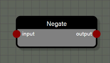
Negate
This is a simple function which changes the sign of the input by multiplying it by -1.0. This node can support Float, Int, Vector2, Vector3, and Vector4 types. The type for the node connected to the input of this node determines the type for the node output.
Properties
- Operation allows this node to be changed to one of the following functions: Cos, Sin, Abs, Exp, Round, Floor, Ceiling, Sqrt, Log, Tan, ArcTan, ArcCos, ArcSin, Sign, Negate, OneMinus, Reciprocal, ToDegrees, or ToRadians.
Inputs
- input is connected to a node providing a value to be used in the function.
Outputs
- output is the transformed value from the input and matches type with the value connected to input.
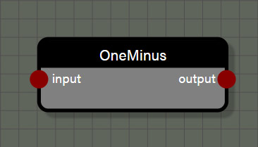
OneMinus
This is a shortcut function which subtracts the input value from 1.0. When this function is applied to a value in the range of 0.0 to 1.0 the result will be an inversion of the input on that scale of 0.0 to 1.0. This node can support Float, Int, Vector2, Vector3, and Vector4 types. The type for the node connected to the input of this node determines the type for the node output.
Properties
- Operation allows this node to be changed to one of the following functions: Cos, Sin, Abs, Exp, Round, Floor, Ceiling, Sqrt, Log, Tan, ArcTan, ArcCos, ArcSin, Sign, Negate, OneMinus, Reciprocal, ToDegrees, or ToRadians.
Inputs
- input is connected to a node providing a value to be used in the function.
Outputs
- output is the transformed value from the input and matches type with the value connected to input.
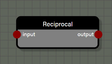
Reciprocal
This is a shortcut function which divides 1.0 by the input value. This node can support Float, Int, Vector2, Vector3, and Vector4 types. The type for the node connected to the input of this node determines the type for the node output.
Properties
- Operation allows this node to be changed to one of the following functions: Cos, Sin, Abs, Exp, Round, Floor, Ceiling, Sqrt, Log, Tan, ArcTan, ArcCos, ArcSin, Sign, Negate, OneMinus, Reciprocal, ToDegrees, or ToRadians.
Inputs
- input is connected to a node providing a value to be used in the function.
Outputs
- output is the transformed value from the input and matches type with the value connected to input.

Round
This is a simple function which transforms the input to the nearest whole number. The nearest whole number is determined by considering the fractional portion of the number. If that fractional portion is greater than or equal to 0.5, the input is transformed into the smallest whole number greater than the input. If the fractional portion is less than 0.5, the input is transformed to the largest whole number less than the input. This node can support Float, Int, Vector2, Vector3, and Vector4 types. The type for the node connected to the input of this node determines the type for the node output.
Properties
- Operation allows this node to be changed to one of the following functions: Cos, Sin, Abs, Exp, Round, Floor, Ceiling, Sqrt, Log, Tan, ArcTan, ArcCos, ArcSin, Sign, Negate, OneMinus, Reciprocal, ToDegrees, or ToRadians.
Inputs
- input is connected to a node providing a value to be used in the function.
Outputs
- output is the transformed value from the input and matches type with the value connected to input.

Sign
This is a simple function to return whether an input is positive, negative, or exactly 0.0. If the input is negative this node will return a value of -1.0. If the input is exactly 0.0, the node will return a value of 0.0. Finally, if the value is positive the node will return a value of 1.0. This node can support Float, Int, Vector2, Vector3, and Vector4 types. The type for the node connected to the input of this node determines the type for the node output.
Properties
- Operation allows this node to be changed to one of the following functions: Cos, Sin, Abs, Exp, Round, Floor, Ceiling, Sqrt, Log, Tan, ArcTan, ArcCos, ArcSin, Sign, Negate, OneMinus, Reciprocal, ToDegrees, or ToRadians.
Inputs
- input is connected to a node providing a value to be used in the function.
Outputs
- output returns -1.0 for a negative value in input, 0.0 for a value of 0.0 in input, and 1.0 for a positive value in input.

Square Root
This is a simple function to return the principle square root of a nonnegative value connected to the input port. This node can support Float, Int, Vector2, Vector3, and Vector4 types. The type for the node connected to the input of this node determines the type for the node output.
Properties
- Operation allows this node to be changed to one of the following functions: Cos, Sin, Abs, Exp, Round, Floor, Ceiling, Sqrt, Log, Tan, ArcTan, ArcCos, ArcSin, Sign, Negate, OneMinus, Reciprocal, ToDegrees, or ToRadians.
Inputs
- input is connected to a node providing a value to be used in the function.
Outputs
- output is the principle square root of the input value in a type that matches the input value type.

Subtract
This is a simple math node which subtracts the right input from the left input. This node can support Float, Int, Vector2, Vector3, and Vector4 types, though the node cannot add mixed types. The type of the node first connected to an input determines the type for the node output.
Properties
- Operation allows this node to be changed to one of the following operations: Add, Subtract, Multiply, Divide, Min, or Max.
Inputs
- left is connected to a node providing the first value to be used in the operation.
- right is connected to a node providing the second value to be used in the operation.
Outputs
- output is the difference of the right input subtracted from the left input and matches type with the values connected to left and right.
Math: Scientific
These nodes are a collection of more complex mathematical functions, mostly trigonometric. They are all very straight forward nodes with one input and one output. All nodes in this set can support Float, Int, Vector2, Vector3, and Vector4 types.

Abs
This is a simple function to return the absolute value of the input, which is always a positive value. This node can support Float, Int, Vector2, Vector3, and Vector4 types. The type for the node connected to the input of this node determines the type for the node output.
Properties
- Operation allows this node to be changed to one of the following functions: Cos, Sin, Abs, Exp, Round, Floor, Ceiling, Sqrt, Log, Tan, ArcTan, ArcCos, ArcSin, Sign, Negate, OneMinus, Reciprocal, ToDegrees, or ToRadians.
Inputs
- input is connected to a node providing a value to be used in the function.
Outputs
- output is the absolute value of the input value in a type that matches the input value type.
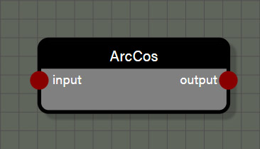
ArcCos
This function returns the inverse cosine of the input value. This node can support Float, Int, Vector2, Vector3, and Vector4 types. The type for the node connected to the input of this node determines the type for the node output.
Properties
- Operation allows this node to be changed to one of the following functions: Cos, Sin, Abs, Exp, Round, Floor, Ceiling, Sqrt, Log, Tan, ArcTan, ArcCos, ArcSin, Sign, Negate, OneMinus, Reciprocal, ToDegrees, or ToRadians.
Inputs
- input is connected to a node providing a value in radians to be used in the function.
Outputs
- output is the inverse cosine of the input value in a type that matches the input value type.

ArcSin
This function returns the inverse sine of the input value. This node can support Float, Int, Vector2, Vector3, and Vector4 types. The type for the node connected to the input of this node determines the type for the node output.
Properties
- Operation allows this node to be changed to one of the following functions: Cos, Sin, Abs, Exp, Round, Floor, Ceiling, Sqrt, Log, Tan, ArcTan, ArcCos, ArcSin, Sign, Negate, OneMinus, Reciprocal, ToDegrees, or ToRadians.
Inputs
- input is connected to a node providing a value in radians to be used in the function.
Outputs
- output is the inverse sine of the input value in a type that matches the input value type.
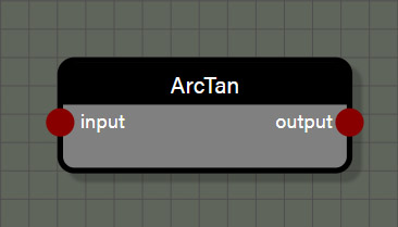
ArcTan
This function returns the inverse tangent of the input value. This node can support Float, Int, Vector2, Vector3, and Vector4 types. The type for the node connected to the input of this node determines the type for the node output.
Properties
- Operation allows this node to be changed to one of the following functions: Cos, Sin, Abs, Exp, Round, Floor, Ceiling, Sqrt, Log, Tan, ArcTan, ArcCos, ArcSin, Sign, Negate, OneMinus, Reciprocal, ToDegrees, or ToRadians.
Inputs
- input is connected to a node providing a value in radians to be used in the function.
Outputs
- output is the inverse tangent of the input value in a type that matches the input value type.

Cos
This function returns the cosine of the input and assumes radians for the input value. This node can support Float, Int, Vector2, Vector3, and Vector4 types. The type for the node connected to the input of this node determines the type for the node output.
Properties
- Operation allows this node to be changed to one of the following functions: Cos, Sin, Abs, Exp, Round, Floor, Ceiling, Sqrt, Log, Tan, ArcTan, ArcCos, ArcSin, Sign, Negate, OneMinus, Reciprocal, ToDegrees, or ToRadians.
Inputs
- input is connected to a node providing a value in radians to be used in the function.
Outputs
- output is the cosine of the input value in a type that matches the input value type.

Exp
This function returns the base of the natural logarithm, approximately 2.718, raised to the power of the input value. This node can support Float, Int, Vector2, Vector3, and Vector4 types. The type for the node connected to the input of this node determines the type for the node output.
Properties
- Operation allows this node to be changed to one of the following functions: Cos, Sin, Abs, Exp, Round, Floor, Ceiling, Sqrt, Log, Tan, ArcTan, ArcCos, ArcSin, Sign, Negate, OneMinus, Reciprocal, ToDegrees, or ToRadians.
Inputs
- input is connected to a node providing a value to be used as the exponent in the function.
Outputs
- output is a nonnegative number representing the base of the natural logarithm raised to the power of the input value in a type that matches the input value type.
Log
This function returns a value representing the power that the base of the natural logarithm, approximately 2.718, is raised to equal the input value. This node can support Float, Int, Vector2, Vector3, and Vector4 types. The type for the node connected to the input of this node determines the type for the node output.
Properties
- Operation allows this node to be changed to one of the following functions: Cos, Sin, Abs, Exp, Round, Floor, Ceiling, Sqrt, Log, Tan, ArcTan, ArcCos, ArcSin, Sign, Negate, OneMinus, Reciprocal, ToDegrees, or ToRadians.
Inputs
- input is connected to a node providing a value to be used in the function.
Outputs
- output is a number representing the power that the base of the natural logarithm, approximately 2.718, is raised to equal the input value in a type that matches the input value type.

Sin
This function returns the sine of the input and assumes radians for the input value. This node can support Float, Int, Vector2, Vector3, and Vector4 types. The type for the node connected to the input of this node determines the type for the node output.
Properties
- Operation allows this node to be changed to one of the following functions: Cos, Sin, Abs, Exp, Round, Floor, Ceiling, Sqrt, Log, Tan, ArcTan, ArcCos, ArcSin, Sign, Negate, OneMinus, Reciprocal, ToDegrees, or ToRadians.
Inputs
- input is connected to a node providing a value in radians to be used in the function.
Outputs
- output is the sine of the input value in a type that matches the input value type.
Tan
This function returns the tangent of the input and assumes radians for the input value. This node can support Float, Int, Vector2, Vector3, and Vector4 types. The type for the node connected to the input of this node determines the type for the node output.
Properties
- Operation allows this node to be changed to one of the following functions: Cos, Sin, Abs, Exp, Round, Floor, Ceiling, Sqrt, Log, Tan, ArcTan, ArcCos, ArcSin, Sign, Negate, OneMinus, Reciprocal, ToDegrees, or ToRadians.
Inputs
- input is connected to a node providing a value in radians to be used in the function.
Outputs
- output is the tangent of the input value in a type that matches the input value type.
ToDegrees
This function converts the input value from radians to degrees. This node can support Float, Int, Vector2, Vector3, and Vector4 types. The type for the node connected to the input of this node determines the type for the node output.
Properties
- Operation allows this node to be changed to one of the following functions: Cos, Sin, Abs, Exp, Round, Floor, Ceiling, Sqrt, Log, Tan, ArcTan, ArcCos, ArcSin, Sign, Negate, OneMinus, Reciprocal, ToDegrees, or ToRadians.
Inputs
- input is connected to a node providing a value in radians to be used in the function.
Outputs
- output is the conversion of input value in radians to a value using degrees in a type that matches the input value type.
ToRadians
This function converts the input value from degrees to radians. This node can support Float, Int, Vector2, Vector3, and Vector4 types. The type for the node connected to the input of this node determines the type for the node output.
Properties
- Operation allows this node to be changed to one of the following functions: Cos, Sin, Abs, Exp, Round, Floor, Ceiling, Sqrt, Log, Tan, ArcTan, ArcCos, ArcSin, Sign, Negate, OneMinus, Reciprocal, ToDegrees, or ToRadians.
Inputs
- input is connected to a node providing a value in degrees to be used in the function.
Outputs
- output is the conversion of input value in degrees to a value using radians in a type that matches the input value type.
Math: Vector
These nodes are used to transform or convert vectors derived from geometry or user defined. As the name of the category suggests, these nodes support Vector2, Vector3, and Vector4 types.
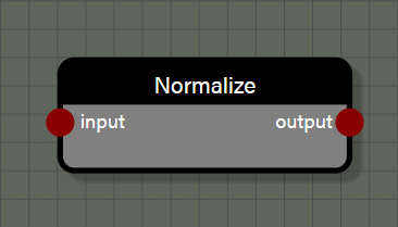
Normalize
This function transforms the input vector into a unit vector of length 1.0. This node can support Vector2, Vector3, and Vector4 types. The type for the node connected to the input of this node determines the type for the node output.
Inputs
- input is connected to a node providing a vector to be used in the function.
Outputs
- output is the unit vector of length 1.0 transformed from the input vector in a type that matches the input value type.
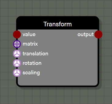
Transform
This function transforms the input geometry using either a custom Matrix or a Vector3 input for translation, rotation, and scaling. The required input for this node is the geometry input and the output will also be geometry. The rest of the inputs are optional, but if providing a Matrix input to the node, the translation, rotation, and scale inputs will be ignored as the Matrix takes precedence over the individual transform inputs.
Properties
- translation is an input field for a Vector3 value to be used to translate the position of the geometry. This property is only visible if there is no wire connected to the translation input.
- rotation is an input field for a Vector3 value in radians to be used to set the rotation of the geometry. This property is only visible if there is no wire connected to the rotation input.
- scaling is an input field for a Vector3 value to be used to set the scale of the geometry. This property is only visible if there is no wire connected to the scaling input.
Advanced
- Evaluate context is used for optimization in the graph when using successive iterable nodes. If this property is set to true, each iteration in this node will also calculate all looped context feeding this node. If there are several iterable nodes connected in sequence, the calculations become exponential with every iteration of the current node calculating every iteration of the previous node back to the beginning of the chain. This can cause a spike in process time in the graph. Disabling evaluate context will prevent nodes from initiating evaluations of previous context each iteration which will greatly speed up the graph. However, since there may be a case where it is desireable to re-evaluate context with each iteration of a node, this parameter is available to the user and defaults to true. If a graph seems to be taking too long to process, check iterable nodes to see if disabling the evaluation of context will help improve performance.
Inputs
- value is connected to a node providing the geometry to be used in the function.
- matrix is connected to a node providing a custom Matrix to be used in the transformation. This can be a manually constructed Matrix or another node that provides a Matrix such as RotationX.
- translation is connected to a node providing a Vector3 value to be used to translate the position of the geometry.
- rotation is connected to a node providing a Vector3 value in radians to be used to set the rotation of the geometry.
- scaling is connected to a node providing a Vector3 value to be used to set the scale of the geometry.
Outputs
- output is the geometry after transformation and is always type geometry.
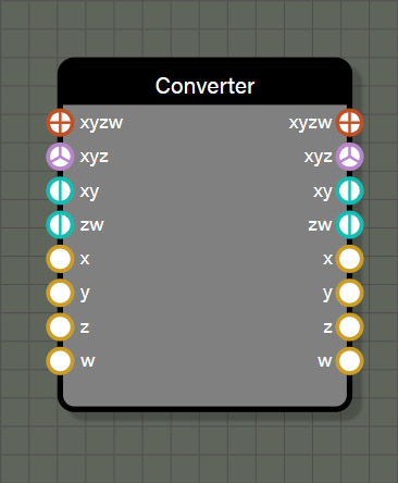
VectorConverter
This node is used to either split a vector into its components or assemble components into a vector. This node has a lot of utility for introducing a change into one or more components of a vector based on the need of the user. It can also be used to swizzle components or assemble components in several ways to make up a vector. Each input will override the narrower inputs below it. For example, a Vector4 connected to the xyzw input will override any values connected to xyz, xy, zw, x, y, z, or w. The process is the same for each input so any value connected to the xy input will override any values connected to the x and y inputs.
The values provided by the outputs depend entirely on the values connected to the inputs. The node will work from the top input down and assemble a Vector4 value which can then be referenced from any of the outputs. If there is a component of the Vector4 output that was not defined in the input, the value of that component will be 0.0. This means if you only connect values to the x, y, and z inputs there will still be a Vector4 value available in the xyzw output that has 0.0 for the value of w. Since the inputs work from the top down, the VectorConverter will work with various combinations. For example, connecting values to the xy input as well as the z and w inputs will create a complete Vector4 value with no overrides. However, if connecting values to the xyz input as well as the z and w inputs will create a Vector4 of the xyz input and the w input, ignoring the value connected to the z input.
Inputs
- xyzw is connected to a Vector4 value which overrides duplicate channel values lower on the node.
- xyz is connected to a Vector3 value which overrides duplicate channel values lower on the node.
- xy is connected to a Vector2 value which overrides duplicate channel values lower on the node.
- zw is connected to a Vector2 value which overrides duplicate channel values lower on the node.
- x is connected to a Float value.
- y is connected to a Float value.
- z is connected to a Float value.
- w is connected to a Float value.
Outputs
- xyzw returns a Vector4 value made from the input components, assigning 0.0 to any channel not defined by the inputs.
- xyz returns a Vector3 value made from the input components, assigning 0.0 to any channel not defined by the inputs.
- xy returns a Vector2 value made from the input components, assigning 0.0 to any channel not defined by the inputs.
- zw returns a Vector2 value made from the input components, assigning 0.0 to any channel not defined by the inputs.
- x returns a Float value for the x component supplied by the inputs or 0.0 if the channel was not defined by the inputs.
- y returns a Float value for the y component supplied by the inputs or 0.0 if the channel was not defined by the inputs.
- z returns a Float value for the z component supplied by the inputs or 0.0 if the channel was not defined by the inputs.
- w returns a Float value for the w component supplied by the inputs or 0.0 if the channel was not defined by the inputs.
Matrices
These nodes are used to create transformation matrices to transform geometry in a variety of ways. Depending on the node, the inputs expect either Float or Vector3 types but the output for all of these nodes is type Matrix.
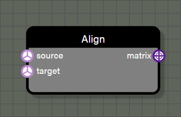
Align
This node generates a rotation matrix to rotate from a source Vector3 to a target Vector3. This node only supports the Vector3 type as input and generates only the Matrix type as an output.
Properties
- source is an input field for a Vector3 value representing the original vector before rotation is applied. This property is only visible if there is no wire connected to the source input.
- target is an input field for a Vector3 value representing the final vector after rotation rotation is applied. This property is only visible if there is no wire connected to the target input.
Inputs
- source is connected to a node providing a Vector3 value representing the original vector before rotation is applied.
- target is connected to a node providing a Vector3 value representing the final vector after rotation rotation is applied.
Outputs
- matrix is the rotation Matrix derived from rotating the source vector to the target vector and can be applied to any matrix transformation input.
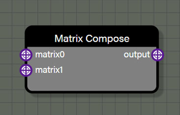
Matrix Compose
This takes two Matrix inputs and composes them into a new Matrix containing both transformations. As expected, the Matrix connected to the matrix0 input is the first transformation and the Matrix connected to matrix1 is the second transformation. If needing to combine more than two transformation matrices, it is possible to chain Matrix Compose nodes by connecting the previous Matrix Compose output to the matrix0 input and a new Matrix to the matrix1 input.
Inputs
- matrix0 is connected to a node providing the first transformation Matrix of the composition.
- matrix1 is connected to a node providing the second transformation Matrix of the composition.
Outputs
- output is the composed transformation Matrix.

RotationX
This node generates a rotation Matrix for rotating geometry around the X axis by a value in radians.
Inputs
- angle is connected to a node providing a Float value in radians to generate the Matrix.
Outputs
- matrix is the transformation Matrix that can be applied to a Transform node attached to geometry.
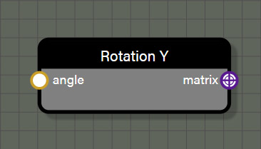
RotationY
This node generates a rotation Matrix for rotating geometry around the Y axis by a value in radians.
Inputs
- angle is connected to a node providing a Float value in radians to generate the Matrix.
Outputs
- matrix is the transformation Matrix that can be applied to a Transform node attached to geometry.

RotationZ
This node generates a rotation Matrix for rotating geometry around the Z axis by a value in radians.
Inputs
- angle is connected to a node providing a Float value in radians to generate the Matrix.
Outputs
- matrix is the transformation Matrix that can be applied to a Transform node attached to geometry.
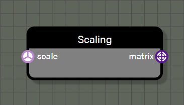
Scaling
This node generates a scaling Matrix for setting the scale of geometry.
Inputs
- scale is connected to a node providing a Vector3 value to generate the Matrix.
Outputs
- matrix is the transformation Matrix that can be applied to a Transform node attached to geometry.
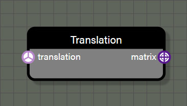
Translation
This node generates a translation Matrix for setting the translation of geometry.
Inputs
- translation is connected to a node providing a Vector3 value to generate the Matrix.
Outputs
- matrix is the transformation Matrix that can be applied to a Transform node attached to geometry.
Instances
These nodes are used to create instances of input geometry in one of several different methods. In all cases, multiple instances of a specific, non-null geometry are created but the differences come in where they are instantiated and how many instances are created. Several of these nodes use a separate piece of geometry to drive position and location for instances, but this can also be done by setting positions and count manually. Each node in this set, however, outputs only the instanced geometry and not the source geometry used to generate positions and/or number of instances. Additionally, these nodes generate a single geometry rather than individual instances, so there is no need to merge them after these nodes.
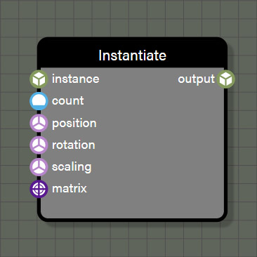
Instantiate
This node generates instances of non-null geometry wired to an input based on the count input. If a null geometry is passed to the node during an iteration, the node will continue to iterate until the required number of non-null instances are created. These instances will be output as a single geometry rather than multiple instanced meshes. The transform of each instance is taken from the matrix input which will override the inputs below it OR is taken from the inputs for position, rotation, and scaling. Like the Vector Converter node, if the matrix input is connected then position, rotation, and scaling are ignored as the matrix input will account for the entire transformation of the instance.
Properties
- count is an input field for an Int value to be used to determine the number of instances to create. This property is only visible if there is no wire connected to the count input.
- translation is an input field for a Vector3 value to be used to translate the position of each instance. This property is only visible if there is no wire connected to the translation input.
- rotation is an input field for a Vector3 value in radians to be used to set the rotation of each instance. This property is only visible if there is no wire connected to the rotation input.
- scaling is an input field for a Vector3 value to be used to set the scale of each instance. This property is only visible if there is no wire connected to the scaling input.
Advanced
- Evaluate context is used for optimization in the graph when using successive iterable nodes. If this property is set to true, each iteration in this node will also calculate all looped context feeding this node. If there are several iterable nodes connected in sequence, the calculations become exponential with every iteration of the current node calculating every iteration of the previous node back to the beginning of the chain. This can cause a spike in process time in the graph. Disabling evaluate context will prevent nodes from initiating evaluations of previous context each iteration which will greatly speed up the graph. However, since there may be a case where it is desireable to re-evaluate context with each iteration of a node, this parameter is available to the user and defaults to true. If a graph seems to be taking too long to process, check iterable nodes to see if disabling the evaluation of context will help improve performance.
Inputs
- instance is connected to a node providing a geometry from which to create instances.
- count is connected to a node providing an Int to set the number of instances to create.
- matrix is connected to a node providing a transformation matrix to set position, rotation, and scaling for each instance.
- position is connected to a node providing a Vector3 to set the position for each instance.
- rotation is connected to a node providing a Vector3 using radians to set the rotation for each instance.
- scaling is connected to a node providing a Vector3 to set the scaling for each instance.
Outputs
- output is the geometry generated from the node. No matter how many instances were created with this node, the output will be a single geometry that has been automatically merged.
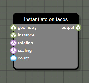
InstantiateOnFaces
This node generates instances of non-null geometry wired to the instance input on this node. If a null geometry is passed to the node during an iteration, the node will continue to iterate until the required number of non-null instances are created. These instances will be output as a single geometry rather than multiple instanced meshes. The instance positions are driven by a source geometry connected to the geometry input. Each instance will be distributed across the available faces of the source mesh. The position of each mesh will be a randomly generated position coplanar with and within the bounds of the target face. If there are fewer instances than faces on the source geometry, not every face will be assigned an instance. However, if there are more instances than faces in the source mesh, each face in the source mesh will be assigned one or more instances. If there is a connection made to the matrix input of this node, the transformation of each instance will be driven from this input. Any connections made to the matrix input will override any connections made to the inputs below it. If nothing is connected to the matrix input, the transformation is taken from any connections to inputs for position, rotation, and scaling.
Properties
- count is an input field for an Int value to be used to determine the number of instances to create. This property is only visible if there is no wire connected to the count input.
- rotation is an input field for a Vector3 value in radians to be used to set the rotation of each instance. This property is only visible if there is no wire connected to the rotation input.
- scaling is an input field for a Vector3 value to be used to set the scale of each instance. This property is only visible if there is no wire connected to the scaling input.
Advanced
- Evaluate context is used for optimization in the graph when using successive iterable nodes. If this property is set to true, each iteration in this node will also calculate all looped context feeding this node. If there are several iterable nodes connected in sequence, the calculations become exponential with every iteration of the current node calculating every iteration of the previous node back to the beginning of the chain. This can cause a spike in process time in the graph. Disabling evaluate context will prevent nodes from initiating evaluations of previous context each iteration which will greatly speed up the graph. However, since there may be a case where it is desireable to re-evaluate context with each iteration of a node, this parameter is available to the user and defaults to true. If a graph seems to be taking too long to process, check iterable nodes to see if disabling the evaluation of context will help improve performance.
Inputs
- geometry is connected to a node providing a source geometry to distribute instances upon.
- instance is connected to a node providing a geometry from which to create instances.
- count is connected to a node providing an Int to set the number of instances to create.
- matrix is connected to a node providing a transformation matrix to set position, rotation, and scaling for each instance.
- rotation is connected to a node providing a Vector3 using radians to set the rotation for each instance.
- scaling is connected to a node providing a Vector3 to set the scaling for each instance.
Outputs
- output is the geometry generated from the node. No matter how many instances were created with this node, the output will be a single geometry that has been automatically merged.
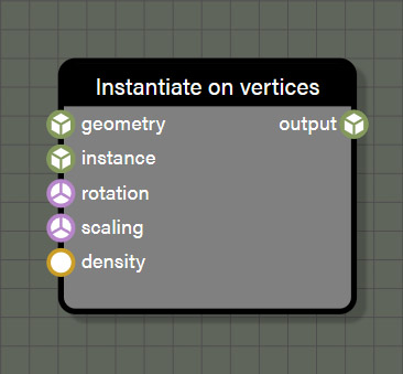
InstantiateOnVertices
This node generates instances of non-null geometry wired to the instance input on this node. If a null geometry is passed to the node during an iteration, the node will continue to iterate until the required number of non-null instances are created. These instances will be output as a single geometry rather than multiple instanced meshes. The instance positions are driven by a source geometry connected to the geometry input. The number of instances created will be determined by the vertex count of the source geometry and the density input value using a 0.0 - 1.0 range. Density defines the percentage of randomly selected vertices that will have an instance created at its position and each will receive exactly one instance. If there is a connection made to the matrix input of this node, the transformation of each instance will be driven from this input. Any connections made to the matrix input will override any connections made to the inputs below it. If nothing is connected to the matrix input, the transformation is taken from any connections to inputs for position, rotation, and scaling.
Properties
- density is an input field for a float value with a range of 0.0 - 1.0 which determines the percentage of randomly selected vertices that are eligible to for an instance. This property is only visible if there is no wire connected to the count input.
- rotation is an input field for a Vector3 value in radians to be used to set the rotation of each instance. This property is only visible if there is no wire connected to the rotation input.
- scaling is an input field for a Vector3 value to be used to set the scale of each instance. This property is only visible if there is no wire connected to the scaling input.
Advanced
- Evaluate context is used for optimization in the graph when using successive iterable nodes. If this property is set to true, each iteration in this node will also calculate all looped context feeding this node. If there are several iterable nodes connected in sequence, the calculations become exponential with every iteration of the current node calculating every iteration of the previous node back to the beginning of the chain. This can cause a spike in process time in the graph. Disabling evaluate context will prevent nodes from initiating evaluations of previous context each iteration which will greatly speed up the graph. However, since there may be a case where it is desireable to re-evaluate context with each iteration of a node, this parameter is available to the user and defaults to true. If a graph seems to be taking too long to process, check iterable nodes to see if disabling the evaluation of context will help improve performance.
- Remove duplicate positions is used to prevent instances from being assigned to vertices that share the same position with another vertex in the source geometry.
Inputs
- geometry is connected to a node providing a source geometry to distribute instances upon.
- instance is connected to a node providing a geometry from which to create instances.
- density is connected to a node providing an Float value in a range of 0.0 - 1.0 which determines the percentage of randomly selected vertices that are eligible for an instance.
- matrix is connected to a node providing a transformation matrix to set position, rotation, and scaling for each instance.
- rotation is connected to a node providing a Vector3 using radians to set the rotation for each instance.
- scaling is connected to a node providing a Vector3 to set the scaling for each instance.
Outputs
- output is the geometry generated from the node. No matter how many instances were created with this node, the output will be a single geometry that has been automatically merged.
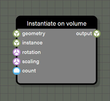
InstantiateOnVolume
This node generates instances of non-null geometry wired to the instance input on this node. If a null geometry is passed to the node during an iteration, the node will continue to iterate until the required number of non-null instances are created. These instances will be output as a single geometry rather than multiple instanced meshes. The instance positions are driven by a source geometry connected to the geometry input. All instances created will be positioned randomly within the source mesh volume. The number of instances created will be determined by the value connected to the count input on the node. If there is a connection made to the matrix input of this node, the transformation of each instance will be driven from this input. Any connections made to the matrix input will override any connections made to the inputs below it. If nothing is connected to the matrix input, the transformation is taken from any connections to inputs for position, rotation, and scaling.
Note that this node needs to make several ray casts to ensure all instances fall within the volume of the source mesh so this node can be quite slow. Keeping the source mesh simple and the number of instances few will help optimize the time this node requires, but expect this node to be resource intensive whenever it is used.
Properties
- count is an input field for an Int value to be used to determine the number of instances to create. This property is only visible if there is no wire connected to the count input.
- rotation is an input field for a Vector3 value in radians to be used to set the rotation of each instance. This property is only visible if there is no wire connected to the rotation input.
- scaling is an input field for a Vector3 value to be used to set the scale of each instance. This property is only visible if there is no wire connected to the scaling input.
Advanced
- Evaluate context is used for optimization in the graph when using successive iterable nodes. If this property is set to true, each iteration in this node will also calculate all looped context feeding this node. If there are several iterable nodes connected in sequence, the calculations become exponential with every iteration of the current node calculating every iteration of the previous node back to the beginning of the chain. This can cause a spike in process time in the graph. Disabling evaluate context will prevent nodes from initiating evaluations of previous context each iteration which will greatly speed up the graph. However, since there may be a case where it is desireable to re-evaluate context with each iteration of a node, this parameter is available to the user and defaults to true. If a graph seems to be taking too long to process, check iterable nodes to see if disabling the evaluation of context will help improve performance.
Inputs
- geometry is connected to a node providing a source geometry to distribute instances upon.
- instance is connected to a node providing a geometry from which to create instances.
- density is connected to a node providing an Float value in a range of 0.0 - 1.0 which determines the percentage of randomly selected vertices that are eligible for an instance.
- matrix is connected to a node providing a transformation matrix to set position, rotation, and scaling for each instance.
- rotation is connected to a node providing a Vector3 using radians to set the rotation for each instance.
- scaling is connected to a node providing a Vector3 to set the scaling for each instance.
Outputs
- output is the geometry generated from the node. No matter how many instances were created with this node, the output will be a single geometry that has been automatically merged.
Misc
These nodes are largely to help with organization and debugging a graph, but there is also some utility to be found in them. Node graphs are notorious for being difficult to read once they get complex due to the spaghetti of wires that often occurs within large graphs. That's where both the teleport nodes and the elbow node come in. These nodes help reduce some of the wire complexity in graphs, making them much easier to read. Debugging the graph can also be challenging especially when large arrays of values are being pushed through the graph. The debug node is crucial for being able to see values passed along any wire at any point. Lastly, the GeometryInfo node can be used as easily to debug the graph as it can to drive logic within.
Debug
The debug node is a very simple node that can be connected to Float, Int, Vector2, Vector3, Vector4, and Matrix types. While the node can be manually connected between two nodes, simply dropping a debug from the graph on an existing wire of a supported type will automatically connect the node in the middle of the existing wire. Alternatively a debug node can be inserted into an existing wire simply by holding crtl and left clicking any compatible wire. And while these methods of quickly inserting a debug node require it to be inserted between two nodes, the debug node does not require a connection to its output to function. It can be a terminal node in the graph if needed to debug a value that isn't easily connected back to the graph flow.
The node doesn't do any calculations in the graph, only displays the values carried along the wire in the properties panel. Simply select the node and the panel will display whatever value is being passed. This also works for iterable nodes that may contain an array of values. Since the debug node is only used to display information in the UI, there is no cost to the node and debug nodes can be left within a graph much like an elbow node if desired.
Note: There will be times when the display of debug values will be truncated due to the length of the values not fitting within the width of the UI panel. If this happens, simply hover the cursor over any displayed value and a tooltip will appear showing the value in its entirety.
Inputs
- input can be connected to a node providing a Float, Int, Vector2, Vector3, Vector4, or Matrix type.
Outputs
- output is a passthrough of the value connected to input of the same type. Note that the debug node only works if it is connected to a path that reaches the GeometryOutput node. If the output does not connect to GeometryOutput at some point, this node won't be evaluated and will not show any debug values when selected.
Elbow
The elbow node is an organizational node to help route wires within a graph. It is a passthrough node that supports Float, Int, Vector2, Vector3, Vector4, Matrix, and Geometry types. The use for this node is just to re-route wires to help with graph organization and it adds no time to the graph calculations so many can be used with no sacrifice to performance. Elbow nodes can be used sequentially as well to perform multiple bends in a wire to detour around congested areas of the graph. Like any other node, an elbow also supports multiple connections to its output port so it can be used to split one wire into many when needed.
Inputs
- input can be connected to a node providing a Float, Int, Vector2, Vector3, Vector4, Matrix, or Geometry type.
Outputs
- output is a passthrough of the value connected to input of the same type.
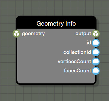
GeometryInfo
This node is also a passthrough node for the Geometry type which adds no time to a graph. It does perform one important task which is supplying access to information about the associated geometry at this specific point of the graph. There may be need to access information like vertex count for debugging purposes which can be fed directly to a debug node. Alternatively, the collectionID of the geometry might be needed to help drive logic in the graph through nodes like equal. This node is flexible enough to fit many different needs which is why it has been added to this group.
Inputs
- input can be connected to a node providing a Geometry type.
Outputs
- output is a passthrough of the Geometry type connected to input.
- id is an Int representing the ID of the current Geometry.
- collectionID is an Int representing the ID assigned to this Geometry by a collection to which it is assigned.
- verticesCount is an Int representing the total number of vertices in this Geometry.
- facesCount is an Int representing the total number of faces in this Geometry.
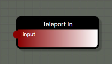
TeleportIn
This node is an organizational node to help reduce the complexity of overlapping wires within a graph. It is a passthrough node that supports all data types. This node works in conjunction with the TeleportOut node to make a connection, often far across a graph, without the need for a wire. This node can be connected to any node to create a reference to the value passed by the connected node. When connecting the TeleportIn node to another node, it is important to rename this node to a unique name as this name will be referenced by the TeleportOut node. On the TeleportOut node, selecting the name used by this node as the entry point will create a reference to the value connected to the TeleportIn node. In this way, a single value can be used in several places of a graph without the need to stretch wires across the graph.
Inputs
- input can be connected to a node providing a Float, Int, Vector2, Vector3, Vector4, Matrix, or Geometry type.
TeleportOut
This node is an organizational node to help reduce the complexity of overlapping wires within a graph. It is a passthrough node that supports Float, Int, Vector2, Vector3, Vector4, Matrix, and Geometry types. This node works in conjunction with the TeleportIn node to make a connection, often far across a graph, without the need for a wire. Setting the entry point property on this node will tell the node which value to reference. Each TeleportIn node in the graph will be available to the TeleportOut node and it can be changed just by selecting a new entry point if needed. In this way, a single value can be used in several places of a graph without the need to stretch wires across the graph.
Properties
- Entry point is the specific TeleportIn node that is referenced by this node.
Outputs
- output is the value referenced by the selected entry point in a type that matches the referenced value.
Updates
These nodes will update connected geometry in one of several ways. It could be assigning it to a collection, merging with other geometry, or setting one of the various properties of geometry like colors, material IDs, normals, positions, tangents, or UVs. These nodes, like the math nodes, are some of the most commonly used nodes as they perform very important operations for creating geometry.
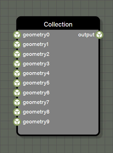
Collection
This node creates a collection of up to 10 geometry inputs. When used in conjunction with one of the instantiate nodes, the collection will provide one random geometry from the collection per iteration of the instantiate node. This allows for more randomization when creating a procedural mesh. The collection also provides a unique collection ID to each included geometry to help drive logic within the graph. The collection ID can be accessed with the GeometryInfo node.
Advanced
- Evaluate context is used for optimization in the graph when using successive iterable nodes. If this property is set to true, each iteration in this node will also calculate all looped context feeding this node. If there are several iterable nodes connected in sequence, the calculations become exponential with every iteration of the current node calculating every iteration of the previous node back to the beginning of the chain. This can cause a spike in process time in the graph. Disabling evaluate context will prevent nodes from initiating evaluations of previous context each iteration which will greatly speed up the graph. However, since there may be a case where it is desireable to re-evaluate context with each iteration of a node, this parameter is available to the user and defaults to true. If a graph seems to be taking too long to process, check iterable nodes to see if disabling the evaluation of context will help improve performance.
Inputs
- geometry0 can optionally be connected to a node providing a Geometry type.
- geometry1 can optionally be connected to a node providing a Geometry type.
- geometry2 can optionally be connected to a node providing a Geometry type.
- geometry3 can optionally be connected to a node providing a Geometry type.
- geometry4 can optionally be connected to a node providing a Geometry type.
- geometry5 can optionally be connected to a node providing a Geometry type.
- geometry6 can optionally be connected to a node providing a Geometry type.
- geometry7 can optionally be connected to a node providing a Geometry type.
- geometry8 can optionally be connected to a node providing a Geometry type.
- geometry9 can optionally be connected to a node providing a Geometry type.
Outputs
- output is a randomly selected geometry from those available through connected inputs.
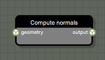
ComputeNormals
There are times when it is necessary to recompute normals when creating geometry. This node is simply there to handle any computations of normals that are needed.
Inputs
- geometry is connected to a node providing a Geometry type.
Outputs
- output is the geometry after computing normals.
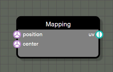
Mapping
When working with geometry, it is often necessary to create a new UV mapping for it such as when the geometry has been optimized or if an additional UV set is desired. This node will create new set of UV coordinates for the geometry based on the projection method selected. The available projections are spherical, cylindrical, and cubic and more may be added in the future. Simply pass the positions contextual value to the position input and a Vector3 to the center input to define the center of the projection and create UV coordinates for each vertex.
Advanced
- Mapping defines the projection method for mapping UV coordinates from the available options of spherical, cylindrical, and cubic.
Inputs
- positions is connected to the positions contextual value node to provide the vertex list to the node.
- center is connected to a node a Vector3 position for the center of the projection.
Outputs
- uv is the geometry after computing normals.
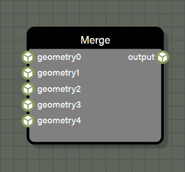
Merge
A common operation when creating procedural geometry is to merge two or more different meshes. This node will merge up to five geometry inputs into one using a simple merge. This node does not do any type of boolean operation and does not change the vertex lists or UV coordinates at all. If multiple meshes are merged which have different material IDs, a MultiMaterial will be created and assigned to keep the original material breaks of each geometry. When using the Merge node, please note that the advanced property Evaluate Context is disabled by default for performance reasons. If the prior context is not evaluated then any procedural generation of values done before the merge node will be executed only once. If the output of that merge node is then used in any instantiate loop, all instances will be exactly the same. If it is desired that merged geometry built procedurally be unique with each instance, the Evaluate Context property on the Merge node must be enabled. Remember that enabling Evaluate Context on a merge node will increase the time needed to generate the final geometry, so it is important to be prudent on how many nodes must be evaluated before merging, especially if the output of the merge is then used as the source for instancing.
Advanced
- Evaluate context is used for optimization in the graph when using successive iterable nodes. If this property is set to true, each iteration in this node will also calculate all looped context feeding this node. If there are several iterable nodes connected in sequence, the calculations become exponential with every iteration of the current node calculating every iteration of the previous node back to the beginning of the chain. This can cause a spike in process time in the graph. Disabling evaluate context will prevent nodes from initiating evaluations of previous context each iteration which will greatly speed up the graph. However, since there may be a case where it is desireable to re-evaluate context with each iteration of a node, this parameter is available to the user and defaults to true. If a graph seems to be taking too long to process, check iterable nodes to see if disabling the evaluation of context will help improve performance.
Inputs
- geometry0 can optionally be connected to a node providing a Geometry type.
- geometry1 can optionally be connected to a node providing a Geometry type.
- geometry2 can optionally be connected to a node providing a Geometry type.
- geometry3 can optionally be connected to a node providing a Geometry type.
- geometry4 can optionally be connected to a node providing a Geometry type.
Outputs
- output is the merged geometry made from those available through connected inputs.
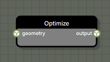
Optimize
There are times when a geometry will have unwelded vertices where multiple vertices occupy the same position. This is common when using glTF files as the specification states that vertices that lie on a UV seam should be split for optimization reasons. If working with geometry that has unwelded vertices that need to be merged, use the optimize node. This node does a simple operation that merges any vertices that share the same position within a certain epsilon. This operation is destructive in that it creates a new triangle list and deletes all vertex parameters other than positions. This means that any mesh that has been optimized will need new normals, tangents, and vertex colors. Typically, the first node connected after an Optimize node would be a ComputeNormals node.
Advanced
- Evaluate context is used for optimization in the graph when using successive iterable nodes. If this property is set to true, each iteration in this node will also calculate all looped context feeding this node. If there are several iterable nodes connected in sequence, the calculations become exponential with every iteration of the current node calculating every iteration of the previous node back to the beginning of the chain. This can cause a spike in process time in the graph. Disabling evaluate context will prevent nodes from initiating evaluations of previous context each iteration which will greatly speed up the graph. However, since there may be a case where it is desireable to re-evaluate context with each iteration of a node, this parameter is available to the user and defaults to true. If a graph seems to be taking too long to process, check iterable nodes to see if disabling the evaluation of context will help improve performance.
- Epsilon is the radius which defines which vertices will be merged. Any vertices within an epsilon of the current vertex will all be merged into one.
Inputs
- geometry is connected to a node providing a Geometry type.
Outputs
- output is the optimized geometry which will no longer have a UV mapping if one existed.
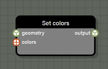
SetColors
This node is one of the several which are responsible for defining geometry properties. This node will set the color of each vertex in the geometry according to the Vector4 value provided to the node.
Advanced
- Evaluate context is used for optimization in the graph when using successive iterable nodes. If this property is set to true, each iteration in this node will also calculate all looped context feeding this node. If there are several iterable nodes connected in sequence, the calculations become exponential with every iteration of the current node calculating every iteration of the previous node back to the beginning of the chain. This can cause a spike in process time in the graph. Disabling evaluate context will prevent nodes from initiating evaluations of previous context each iteration which will greatly speed up the graph. However, since there may be a case where it is desireable to re-evaluate context with each iteration of a node, this parameter is available to the user and defaults to true. If a graph seems to be taking too long to process, check iterable nodes to see if disabling the evaluation of context will help improve performance.
Inputs
- geometry is connected to a node providing a Geometry type.
- colors is connected to a node providing Vector4 color(s) for each vertex in the geometry.
Outputs
- output is the geometry after defining a property with this node.
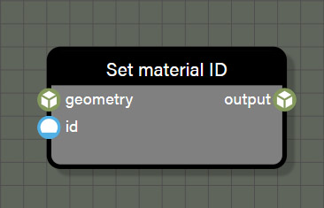
SetMaterialID
This node is one of the several which are responsible for defining geometry properties. This node will set the material ID of each vertex in the geometry according to the Int value provided to the node.
Properties
- id is an input field for an Int value to be used to determine the material ID for the geometry. This property is only visible if there is no wire connected to the ID input.
Advanced
- Evaluate context is used for optimization in the graph when using successive iterable nodes. If this property is set to true, each iteration in this node will also calculate all looped context feeding this node. If there are several iterable nodes connected in sequence, the calculations become exponential with every iteration of the current node calculating every iteration of the previous node back to the beginning of the chain. This can cause a spike in process time in the graph. Disabling evaluate context will prevent nodes from initiating evaluations of previous context each iteration which will greatly speed up the graph. However, since there may be a case where it is desireable to re-evaluate context with each iteration of a node, this parameter is available to the user and defaults to true. If a graph seems to be taking too long to process, check iterable nodes to see if disabling the evaluation of context will help improve performance.
Inputs
- geometry is connected to a node providing a Geometry type.
- id is connected to a node providing a material ID for each vertex in the geometry.
Outputs
- output is the geometry after defining a property with this node.
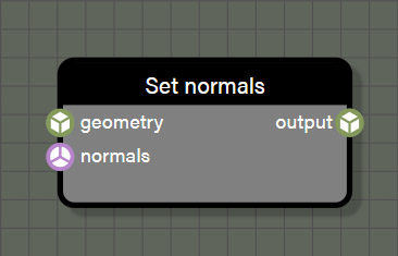
SetNormals
This node is one of the several which are responsible for defining geometry properties. This node will set the normals of each vertex in the geometry according to the Vector3 value provided to the node.
Advanced
- Evaluate context is used for optimization in the graph when using successive iterable nodes. If this property is set to true, each iteration in this node will also calculate all looped context feeding this node. If there are several iterable nodes connected in sequence, the calculations become exponential with every iteration of the current node calculating every iteration of the previous node back to the beginning of the chain. This can cause a spike in process time in the graph. Disabling evaluate context will prevent nodes from initiating evaluations of previous context each iteration which will greatly speed up the graph. However, since there may be a case where it is desireable to re-evaluate context with each iteration of a node, this parameter is available to the user and defaults to true. If a graph seems to be taking too long to process, check iterable nodes to see if disabling the evaluation of context will help improve performance.
Inputs
- geometry is connected to a node providing a Geometry type.
- normals is connected to a node providing Vector3 values for each vertex in the geometry.
Outputs
- output is the geometry after defining a property with this node.
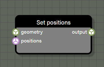
SetPositions
This node is one of the several which are responsible for defining geometry properties. This node will set the positions of each vertex in the geometry according to the Vector3 value provided to the node.
Advanced
- Evaluate context is used for optimization in the graph when using successive iterable nodes. If this property is set to true, each iteration in this node will also calculate all looped context feeding this node. If there are several iterable nodes connected in sequence, the calculations become exponential with every iteration of the current node calculating every iteration of the previous node back to the beginning of the chain. This can cause a spike in process time in the graph. Disabling evaluate context will prevent nodes from initiating evaluations of previous context each iteration which will greatly speed up the graph. However, since there may be a case where it is desireable to re-evaluate context with each iteration of a node, this parameter is available to the user and defaults to true. If a graph seems to be taking too long to process, check iterable nodes to see if disabling the evaluation of context will help improve performance.
Inputs
- geometry is connected to a node providing a Geometry type.
- positions is connected to a node providing Vector3 values for each vertex in the geometry.
Outputs
- output is the geometry after defining a property with this node.
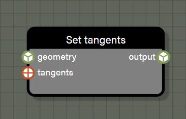
SetTangents
This node is one of the several which are responsible for defining geometry properties. This node will set the tangents of each vertex in the geometry according to the Vector4 value provided to the node.
Advanced
- Evaluate context is used for optimization in the graph when using successive iterable nodes. If this property is set to true, each iteration in this node will also calculate all looped context feeding this node. If there are several iterable nodes connected in sequence, the calculations become exponential with every iteration of the current node calculating every iteration of the previous node back to the beginning of the chain. This can cause a spike in process time in the graph. Disabling evaluate context will prevent nodes from initiating evaluations of previous context each iteration which will greatly speed up the graph. However, since there may be a case where it is desireable to re-evaluate context with each iteration of a node, this parameter is available to the user and defaults to true. If a graph seems to be taking too long to process, check iterable nodes to see if disabling the evaluation of context will help improve performance.
Inputs
- geometry is connected to a node providing a Geometry type.
- tangents is connected to a node providing Vector4 values for each vertex in the geometry.
Outputs
- output is the geometry after defining a property with this node.
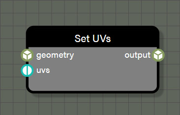
SetUVs
This node is one of the several which are responsible for defining geometry properties. This node will set the UVs of each vertex in the geometry according to the Vector2 value provided to the node. Using this node, a new UV set can be saved to any of the six available UV sets that the engine supports. Simply choose which set is desired in the Texture coordinates index property to assign the UV coordinates to that set.
Advanced
- Evaluate context is used for optimization in the graph when using successive iterable nodes. If this property is set to true, each iteration in this node will also calculate all looped context feeding this node. If there are several iterable nodes connected in sequence, the calculations become exponential with every iteration of the current node calculating every iteration of the previous node back to the beginning of the chain. This can cause a spike in process time in the graph. Disabling evaluate context will prevent nodes from initiating evaluations of previous context each iteration which will greatly speed up the graph. However, since there may be a case where it is desireable to re-evaluate context with each iteration of a node, this parameter is available to the user and defaults to true. If a graph seems to be taking too long to process, check iterable nodes to see if disabling the evaluation of context will help improve performance.
- Texture coordinates index is used to define which of the six supported UV sets should be used when writing this UV mapping.
Inputs
- geometry is connected to a node providing a Geometry type.
- uvs is connected to a node providing Vector2 values for each vertex in the geometry.
Outputs
- output is the geometry after defining a property with this node.
Noises
These nodes are used to create randomize values used for various operations in procedural geometry creation.
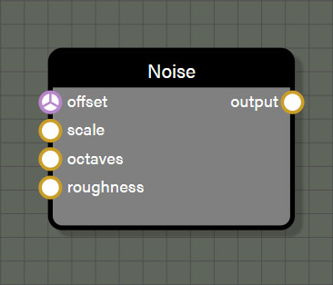
Noise
This node provides a simple 3D Perlin noise to generate a volume of randomized values between 0.0 and 1.0. The properties of the noise can be set to create a range of different value patterns.
Properties
- offset is an input field for a Vector3 value to be used offset the noise texture. This property is only visible if there is no wire connected to the count input.
- scale is an input field for a Float value to be used to scale the noise texture. This property is only visible if there is no wire connected to the rotation input.
- octaves is an input field for a Float value to be used to adjust the number of octaves to the noise texture which increases the frequency of the pattern resulting in increased detail in the texture. This property is only visible if there is no wire connected to the scaling input.
- roughness is an input field for a Float value to be used to adjust the amplitude of the octaves in the noise texture which adds contrast to the texture. This property is only visible if there is no wire connected to the scaling input.
Inputs
- offset is connected to a node providing a Vector3 value to be used offset the noise texture.
- scale is connected to a node providing a Float value to be used to scale the noise texture.
- octaves is connected to a node providing a Float value to be used to adjust the number of octaves to the noise texture which increases the frequency of the pattern resulting in increased detail in the texture.
- roughness is connected to a node providing a Float value to be used to adjust the amplitude of the octaves in the noise texture which adds contrast to the texture.
Outputs
- output is the noise texture as a Float type.
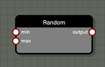
Random
This node provides a random value between a minimum value and a maximum value. This node can support Float, Int, Vector2, Vector3, and Vector4 types. The type for the node connected to the input of this node determines the type for the node output. When using this node with iterable nodes, the node will return a new random value per iteration. Iterable nodes include SetColors, SetNormals, SetPositions, SetTangents, and SetUVs as the operations are performed for every vertex in the geometry. If a random node is used before one of these iterable nodes, a new random value will be generated for each iteration. This is also true for all of the instantiate nodes where the node will loop a certain number of times based on inputs. For more control, the Random node also has an advanced property to lock the value per loop so that the random value will be the same for each iteration or loop. Note that this property only applies to the nearest iteration or loop being performed by a node. This means if a Random node feeds a SetColor node which in turn feeds an Instantiate node, locking the value per loop will apply only to the SetColor node and not the Instantiate node.
Advanced
- Lock per loop will return one value per loop rather than a different random value for each loop when enabled.
Inputs
- min is connected to a node providing a value to be used as the minimum bounds for the random range.
- max is connected to a node providing a value to be used as the maximum bounds for the random range.
Outputs
- output is the random value as a Float type.
Output Nodes
These are required nodes for the graph to create an output geometry.
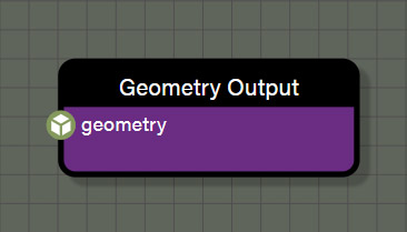
Geometry Output
This node is required to create the geometry and whatever is connected to this node is the final geometry for the graph. This node does not have any special considerations for use, but there are some useful things to know about it. Selecting the node will display useful information about the geometry output that is rendered which include vertices, faces, build time, and sub-meshes. The node also gives stats about if the geometry has normals, vertex colors, UVs and the number of sets, tangents, matrix weights, and matrix indices.
Input
- geometry is connected to a node providing the final geometry for the graph.